HP Superdome SX2000 User Service Guide, Seventh Edition - HP Integrity Superdo - Page 21
Power Sequencing, Enabling 48 Volts, Cooling System, Loads firmware from Compact Flash to RAM.
 |
View all HP Superdome SX2000 manuals
Add to My Manuals
Save this manual to your list of manuals |
Page 21 highlights
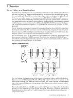
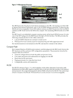
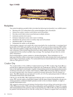
Power Sequencing The power on sequence is as follows: 1. When the main power circuit breaker is turned on, the housekeeping (HKP) voltage turns on first and provides 5.3 V dc to the UGUY, Management Processor (MP), system backplane, cells, and all HIOB. Each BPS provides 5.3 V. 2. When HKP voltage is on the MP performs the following steps: a. De-asserts the Reset and begins to boot SBC. b. Loads VxWorks from flash (can be viewed from the local port). c. Completes the SBC, single board computer hub (SBCH) power-on self-test (POST) begins, and LED start activity appears. d. Loads firmware from Compact Flash to RAM. e. SBCH POST completes. The heartbeat light blinks. USB LEDs turn on later. f. CLU POST and PM POST immediately after power on. 3. After MP POST completes, the MP configures the system. 4. The CLU POST completes. 5. When PM POST completes, the system takes several steps. 6. When the MP finishes the system configuration, it becomes operational and completes several tasks. 7. When the PDHC POST completes, it becomes operational and completes its tasks. When the MP, CLU, and PM PDHC POST completes, utilities entities run their main loops. Enabling 48 Volts The PM must enable +48 V first , but it must obtain permission from the MP. To enable 48 V, the transition cabinet power switch must be moved from OFF to ON. Alternatively you can use the MP Command pe if the power switch is already ON. If the switch is ON, the cabinet wakes up from Power on Reset). If the PM has permission, it sends a PS_CTL_L signal to the FEPS. Then the BPS enables +48 V converters, which send +48 V to the backplane, I/O chassis, HUCB, cells, fans, and blowers. Once the +48 V is enabled, it is cabled to the backplane, cells, and I/O chassis. Cooling System The Superdome has four blowers and five I/O fans per cabinet. These components are all hot-swappable. All have LEDs indicating their current status. Temperature monitoring occurs for the following: • Inlet air for temperature increases above normal • BPS for temperature increases above normal • The I/O power board over temperature signal is monitored The inlet air sensor is on the main cabinet, located near the bottom of cell 1 front. The inlet air sensor and the BPS sensors are monitored by the power monitor 3 (PM3) on the UGUY, and the I/O power board sensors are monitored by the CLU on the UGUY. The PM controls and monitors the speed of groups of N+1 redundant fans. In a CPU cabinet, fan group 0 consists of the four main blowers and fan group 1 consists of the five I/O fans. In an I/O Expansion (IOX) cabinet, fan groups 0-3 consist of four I/O fans and fan group 4 consists of two management subsystem fans. All fans are expected to be populated at all times with the exception of the OLR of a failed fan. The main blowers feature a variable speed control. The blowers operate at full speed; available circuitry can reduce the normal operating speed. All of the I/O fans and managed fans run at one speed. Cooling System 21
-
 1
1 -
2
-
3
-
4
-
5
-
6
-
7
-
8
-
9
-
10
-
11
-
12
-
13
-
14
-
15
-
 16
16 -
 17
17 -
 18
18 -
 19
19 -
 20
20 -
 21
21 -
 22
22 -
 23
23 -
 24
24 -
 25
25 -
 26
26 -
27
-
28
-
29
-
30
-
31
-
32
-
33
-
34
-
35
-
36
-
37
-
38
-
39
-
40
-
41
-
42
-
43
-
44
-
45
-
46
-
47
-
48
-
49
-
50
-
51
-
52
-
53
-
54
-
55
-
56
-
57
-
58
-
59
-
60
-
61
-
62
-
63
-
64
-
65
-
66
-
67
-
68
-
69
-
70
-
71
-
72
-
73
-
74
-
75
-
76
-
77
-
78
-
79
-
80
-
81
-
82
-
83
-
84
-
85
-
86
-
87
-
88
-
89
-
90
-
91
-
92
-
93
-
94
-
95
-
96
-
97
-
98
-
99
-
100
-
101
-
102
-
103
-
104
-
105
-
106
-
107
-
108
-
109
-
110
-
111
-
112
-
113
-
114
-
115
-
116
-
117
-
118
-
119
-
120
-
121
-
122
-
123
-
124
-
125
-
126
-
127
-
128
-
129
-
130
-
131
-
132
-
133
-
134
-
135
-
136
-
137
-
138
-
139
-
140
-
141
-
142
-
143
-
144
-
145
-
146
-
147
-
148
-
149
-
150
-
151
-
152
-
153
-
154
-
155
-
156
-
157
-
158
-
159
-
160
-
161
-
162
-
163
-
164
-
165
-
166
-
167
-
168
-
169
-
170
-
171
-
172
-
173
-
174
-
175
-
176
-
177
-
178
-
179
-
180
-
181
-
182
-
183
-
184
-
185
-
186
-
187
-
188
-
189
-
190
-
191
-
192
-
193
-
194
-
195
-
196
-
197
-
198
-
199
-
200
 |
 |