HP Superdome SX2000 User Service Guide, Seventh Edition - HP Integrity Superdo - Page 198
I/O subsystem, AC0 Present
 |
View all HP Superdome SX2000 manuals
Add to My Manuals
Save this manual to your list of manuals |
Page 198 highlights
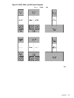
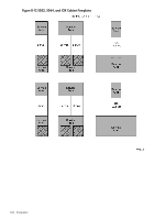
door installation back, 79 front, 79 DP rated power cables, 20 dual in-line memory module, (see DIMM) dual-die processors, 19 E e-Link cable description, 42 ejectors cell board, 110 electrical specifications, 50 electrostatic discharge, 59 EMI panel installing, 111 removing, 89 environmental requirements, 54 equipment returning, 71 equipment footprint templates, 185 external e-Link cable description, 42 F facility guidelines computer room layout, 185 equipment footprint templates, 185 FEPS, 19 description, 20 firmware ACPI interface, 44, 46 EFI interface, 44, 46 event IDs, 44, 46 PAL interface, 44, 46 POSSE shell, 44, 46 SAL interface, 44, 46 front end power supply, (see FEPS) front panel display, 179 G gateway address, 100 global shared memory errors, 48 Gold Book, 112 H halfdome utility connector board, (see HUCB) hardware correctable errors, 48 HKP LED, 179 hot-swap oscillator, (see HSO) housekeeping power front panel display, 96 HKP LED, 96 turning on, 96, 178 housekeeping power LED, 96, 179 HSO detailed description, 28 LED status indications, 28 location on backplane, 29 part of clock subsystem, 27 HUCB 198 Index DIP switch purpose, 18, 24 general description, 25 shown outside system, 25 humidity specifications, 54 I I/O subsystem detailed description, 37 enhanced rope definition, 37 fat rope definition, 37 illustrated I/O backplane slot mapping, 39 PCI-X backplane functionality, 38 SBA chip operation, 38, 39 inspecting cables, 112 circuit boards, 112 installation EMI panel, 111 PDCA, 86 tools required for, 63 visual inspection, 110 intake air filter, 18 interference communications, 59 inventory check, 60 IP address default values, 99 LAN configuration screen, 100 setting private and customer LAN, 99 J JET invoking the software, 108 power cycling after usage, 108 purpose for invoking, 108 JTAG utility for scan test JUST, 108 JUST JTAG utility for scan test, 108 K kick plates attaching to cabinet, 109 shown on cabinet, 109 L LAN port 0, 100 port 1, 100 status, 100 LED AC0 Present, 98, 180 AC1 Present, 98, 180 Attention, 179 HKP (housekeeping), 96, 179 Present, 96, 179 leveling feet attaching, 79 local power monitors, (see LPM)
-
 1
1 -
2
-
3
-
4
-
5
-
6
-
7
-
8
-
9
-
10
-
11
-
12
-
13
-
14
-
15
-
16
-
17
-
18
-
19
-
20
-
21
-
22
-
23
-
24
-
25
-
26
-
27
-
28
-
29
-
30
-
31
-
32
-
33
-
34
-
35
-
36
-
37
-
38
-
39
-
40
-
41
-
42
-
43
-
44
-
45
-
46
-
47
-
48
-
49
-
50
-
51
-
52
-
53
-
54
-
55
-
56
-
57
-
58
-
59
-
60
-
61
-
62
-
63
-
64
-
65
-
66
-
67
-
68
-
69
-
70
-
71
-
72
-
73
-
74
-
75
-
76
-
77
-
78
-
79
-
80
-
81
-
82
-
83
-
84
-
85
-
86
-
87
-
88
-
89
-
90
-
91
-
92
-
93
-
94
-
95
-
96
-
97
-
98
-
99
-
100
-
101
-
102
-
103
-
104
-
105
-
106
-
107
-
108
-
109
-
110
-
111
-
112
-
113
-
114
-
115
-
116
-
117
-
118
-
119
-
120
-
121
-
122
-
123
-
124
-
125
-
126
-
127
-
128
-
129
-
130
-
131
-
132
-
133
-
134
-
135
-
136
-
137
-
138
-
139
-
140
-
141
-
142
-
143
-
144
-
145
-
146
-
147
-
148
-
149
-
150
-
151
-
152
-
153
-
154
-
155
-
156
-
157
-
158
-
159
-
160
-
161
-
162
-
163
-
164
-
165
-
166
-
167
-
168
-
169
-
170
-
171
-
172
-
173
-
174
-
175
-
176
-
177
-
178
-
179
-
180
-
181
-
182
-
183
-
184
-
185
-
186
-
187
-
188
-
189
-
190
-
191
-
192
-
 193
193 -
 194
194 -
 195
195 -
 196
196 -
 197
197 -
 198
198 -
 199
199 -
 200
200
 |
 |
