HP Superdome SX2000 User Service Guide, Seventh Edition - HP Integrity Superdo - Page 52
System Power Requirements, PDCA Locations, Table 2-8 Power Requirements Without SMS
 |
View all HP Superdome SX2000 manuals
Add to My Manuals
Save this manual to your list of manuals |
Page 52 highlights
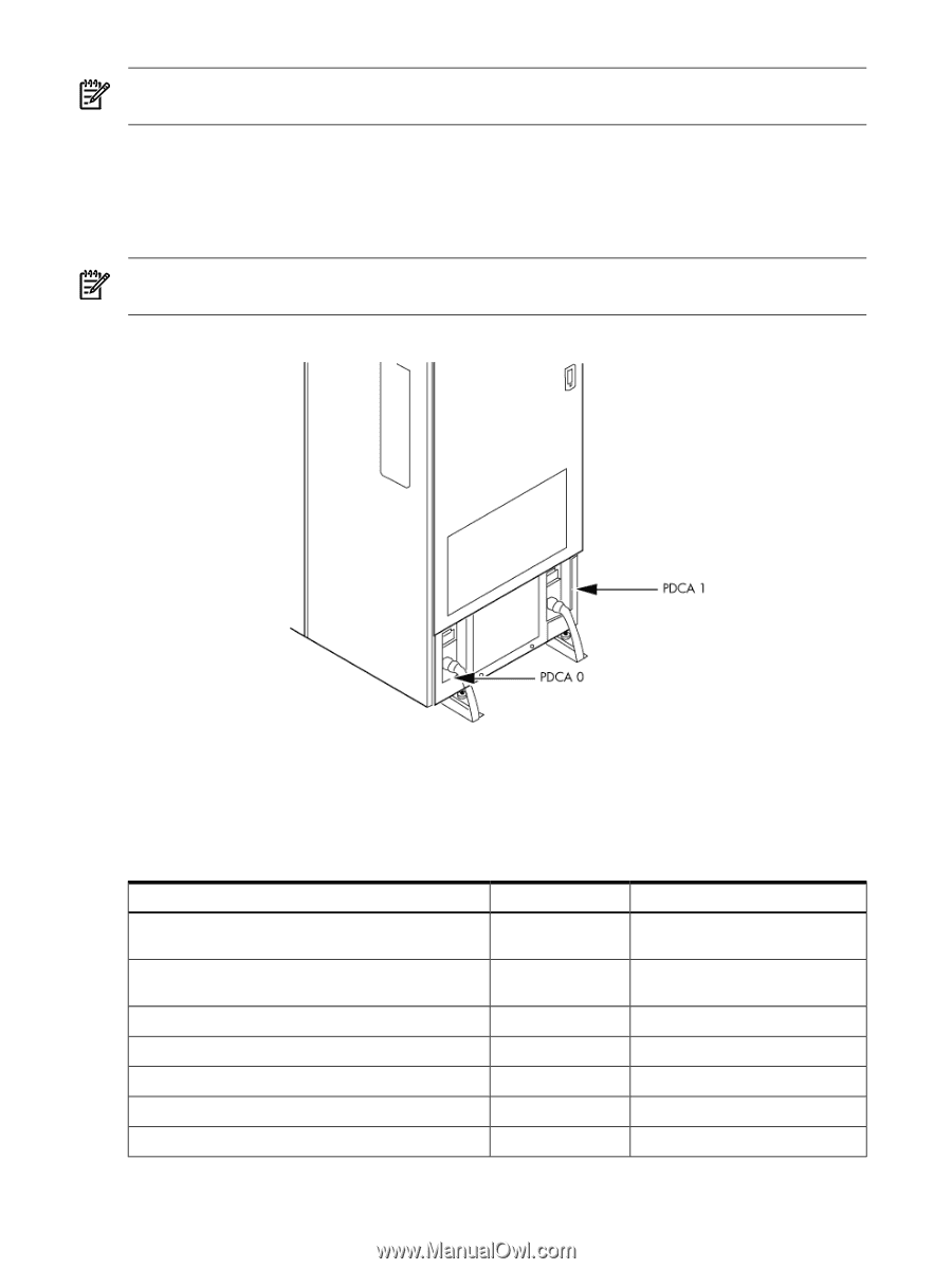
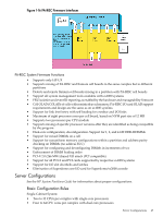
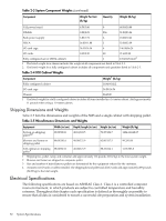
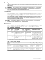
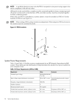
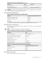
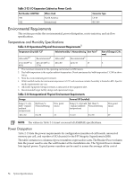
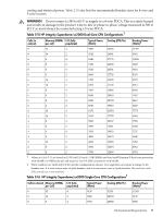
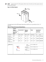
NOTE: A qualified electrician must wire the PDCA receptacle to site power using copper wire and in compliance with all local codes. All branch circuits used within a complex must be connected together to form a common ground. All power sources such as transformers, UPSs, and other sources, must be connected together to form a common ground. When only one PDCA is installed in a system cabinet, it must be installed as PDCA 0. For the location of PDCA 0, see Figure 2-1. NOTE: When wiring a PDCA, phase rotation is unimportant. When using two PDCAs, however, the rotation must be consistent for both. Figure 2-1 PDCA Locations System Power Requirements Table 2-8 and Table 2-9 list the ac power requirements for an HP Integrity Superdome/sx2000 system. These tables provide information to help determine the amount of ac power needed for your computer room. Table 2-8 Power Requirements (Without SMS) Requirement Nominal input voltage Input voltage range (minimum to maximum) Frequency range (minimum to maximum) Number of phases Maximum inrush current Product label maximum current, 3-phase, 4-wire Product label maximum current, 3-phase, 5-wire Value Comments 200/208/220/230/240 V ac rms 200 to 240 V ac rms Autoselecting (measured at input terminals) 50/60 Hz 3 90 A (peak) 44 A rms Per-phase at 200 to 240 V ac 24 A rms Per-phase at 200 to 240 V ac 52 System Specifications
-
 1
1 -
2
-
3
-
4
-
5
-
6
-
7
-
8
-
9
-
10
-
11
-
12
-
13
-
14
-
15
-
16
-
17
-
18
-
19
-
20
-
21
-
22
-
23
-
24
-
25
-
26
-
27
-
28
-
29
-
30
-
31
-
32
-
33
-
34
-
35
-
36
-
37
-
38
-
39
-
40
-
41
-
42
-
43
-
44
-
45
-
46
-
 47
47 -
 48
48 -
 49
49 -
 50
50 -
 51
51 -
 52
52 -
 53
53 -
 54
54 -
 55
55 -
 56
56 -
 57
57 -
58
-
59
-
60
-
61
-
62
-
63
-
64
-
65
-
66
-
67
-
68
-
69
-
70
-
71
-
72
-
73
-
74
-
75
-
76
-
77
-
78
-
79
-
80
-
81
-
82
-
83
-
84
-
85
-
86
-
87
-
88
-
89
-
90
-
91
-
92
-
93
-
94
-
95
-
96
-
97
-
98
-
99
-
100
-
101
-
102
-
103
-
104
-
105
-
106
-
107
-
108
-
109
-
110
-
111
-
112
-
113
-
114
-
115
-
116
-
117
-
118
-
119
-
120
-
121
-
122
-
123
-
124
-
125
-
126
-
127
-
128
-
129
-
130
-
131
-
132
-
133
-
134
-
135
-
136
-
137
-
138
-
139
-
140
-
141
-
142
-
143
-
144
-
145
-
146
-
147
-
148
-
149
-
150
-
151
-
152
-
153
-
154
-
155
-
156
-
157
-
158
-
159
-
160
-
161
-
162
-
163
-
164
-
165
-
166
-
167
-
168
-
169
-
170
-
171
-
172
-
173
-
174
-
175
-
176
-
177
-
178
-
179
-
180
-
181
-
182
-
183
-
184
-
185
-
186
-
187
-
188
-
189
-
190
-
191
-
192
-
193
-
194
-
195
-
196
-
197
-
198
-
199
-
200
 |
 |