HP Superdome SX2000 User Service Guide, Seventh Edition - HP Integrity Superdo - Page 57
Airflow Diagram, Table 2-17 Physical Environmental Specifications, the top of the system.
 |
View all HP Superdome SX2000 manuals
Add to My Manuals
Save this manual to your list of manuals |
Page 57 highlights
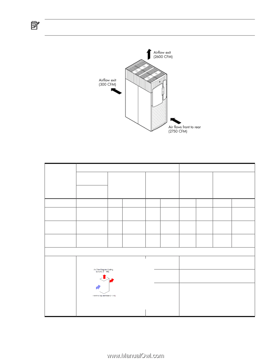
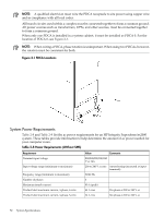
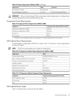
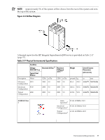
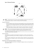
NOTE: Approximately 5% of the system airflow draws from the rear of the system and exits the top of the system. Figure 2-2 Airflow Diagram A thermal report for the HP Integrity Superdome/sx2000 server is provided in Table 2-17 (page 57). Table 2-17 Physical Environmental Specifications Description Minimum Configuration Maximum Configuration Typical Configuration Condition Voltage 200-240 V ac Typical Heat Release Watts 3423 9130 6968 Nominal Airflow 2 Maximum Airflow at 32oC1,2 CFM m3/hr 2900 5.0 2900 5.0 2900 5.0 CFM m3/hr 2900 5.0 2900 5.0 2900 5.0 Weight pounds kg 926.3 420.3 1241.2 563.2 1135.2 515.1 Overall System Dimensions (W X D X H) in mm 30x48x77.2 76.2x121.9x195.6 30x48x77.2 76.2x121.9x195.6 30x48x77.2 76.2x121.9x195.6 ASHRAE Class 1 Minimum 2 Cell, 4 DIMM, 2 I/O Configuration3 Maximum 8 Cell, 32 DIMM, 4 I/O Configuration3 Typical 6 Cell, 16 DIMM, 4 I/O Configuration3 Environmental Requirements 57
-
 1
1 -
2
-
3
-
4
-
5
-
6
-
7
-
8
-
9
-
10
-
11
-
12
-
13
-
14
-
15
-
16
-
17
-
18
-
19
-
20
-
21
-
22
-
23
-
24
-
25
-
26
-
27
-
28
-
29
-
30
-
31
-
32
-
33
-
34
-
35
-
36
-
37
-
38
-
39
-
40
-
41
-
42
-
43
-
44
-
45
-
46
-
47
-
48
-
49
-
50
-
51
-
 52
52 -
 53
53 -
 54
54 -
 55
55 -
 56
56 -
 57
57 -
 58
58 -
 59
59 -
 60
60 -
 61
61 -
 62
62 -
63
-
64
-
65
-
66
-
67
-
68
-
69
-
70
-
71
-
72
-
73
-
74
-
75
-
76
-
77
-
78
-
79
-
80
-
81
-
82
-
83
-
84
-
85
-
86
-
87
-
88
-
89
-
90
-
91
-
92
-
93
-
94
-
95
-
96
-
97
-
98
-
99
-
100
-
101
-
102
-
103
-
104
-
105
-
106
-
107
-
108
-
109
-
110
-
111
-
112
-
113
-
114
-
115
-
116
-
117
-
118
-
119
-
120
-
121
-
122
-
123
-
124
-
125
-
126
-
127
-
128
-
129
-
130
-
131
-
132
-
133
-
134
-
135
-
136
-
137
-
138
-
139
-
140
-
141
-
142
-
143
-
144
-
145
-
146
-
147
-
148
-
149
-
150
-
151
-
152
-
153
-
154
-
155
-
156
-
157
-
158
-
159
-
160
-
161
-
162
-
163
-
164
-
165
-
166
-
167
-
168
-
169
-
170
-
171
-
172
-
173
-
174
-
175
-
176
-
177
-
178
-
179
-
180
-
181
-
182
-
183
-
184
-
185
-
186
-
187
-
188
-
189
-
190
-
191
-
192
-
193
-
194
-
195
-
196
-
197
-
198
-
199
-
200
 |
 |