HP Superdome SX2000 User Service Guide, Seventh Edition - HP Integrity Superdo - Page 22
Utilities Subsystem, Platform Management
 |
View all HP Superdome SX2000 manuals
Add to My Manuals
Save this manual to your list of manuals |
Page 22 highlights
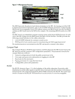
One minute after setting the main blower fan Reference to the desired speed or powering on the cabinet, the PM uses the tach select register to cycle through each fan and measure its speed. When a fan is selected, Timer 1 is used in counter mode to count the pulses on port T1 over a period of one second. If the frequency does not equal the expected frequency plus some margin of error, the fan is considered to have failed and is subtracted from the working fan count. If the failure causes a transition to N- I/O or main fans in a CPU cabinet, the cabinet is immediately powered off. If the failure causes a transition to N- I/O fans in an IOX cabinet, the I/O backplanes contained in the I/O Chassis Enclosure (ICE) containing that fan group are immediately powered off. Only inlet temperature increases are monitored by HP-UX; all other high temperature increase chassis codes do not activate the envd daemon to act as configured in the /etc/envd.conf file. The PM monitors ambient inlet temperature. The PM polls an analog-to-digital converter to read the current ambient temperature. The temperature falls into one of four ranges: Normal, OverTempLow, OverTempMid, or OverTempHigh. The following state codes describe the actions taken based on the various temperature state transitions: OTL_THRESHOLD = 32C -----> Send error code PDC_IPR_OLT OTM_THRESHOLD = 38C ----> Send error code PDC_INT_OTM OTH_THRESHOLD = 40C -----> Shut down 48 V NOTE: In an IOX cabinet, the thresholds are set two degrees higher to compensate for the fact that the cabinet sensor is mounted in a hot spot. Utilities Subsystem The Superdome utilities subsystem is comprised of a number of hardware and firmware components located throughout the Superdome system. Platform Management The sx2000 platform management subsystem consists of a number of hardware and firmware components located throughout the sx2000 system. The sx2000 uses the sx1000 platform management components, with firmware changes to support new functionality. The following list describes the major hardware components of the platform management subsystem and the changes required for the sx2000: The PDH microcontroller is located on each cell PDH daughtercard assembly. It provides communication between the management firmware, the PDH space, and the USB bus. The microcontroller represents a change from the prior implementation, Intel® 80C251 processes, to a more powerful 16-bit microcontroller. This microcontroller change enables the PDH daughtercard design to be compatible across all three new CEC platforms. It also enables the extra processing power to be used to move the console UARTs into PDH memory space located on the cell, eliminating the sx1000 core I/O (CIO) card. The UGUY on Superdome contains the PM, the CLU, and the system clock source circuitry. The CLU circuitry on the UGUY assembly provides cabinet-level cable interconnect for backplane, I/O card cage utility signal communication, and scan support. The PM circuitry on the UGUY assembly monitors and controls the 48 V dc, the cabinet environment (ambient temperature and fans), and controls power to the entities (cells and I/O bays). The MP is a single board computer (SBC) that controls the console (local and remote), the front panel display and its redirection on the console, maintains logs for the event IDs, coordinates messages between devices, and performs other service processor functions. The SBCH board provides USB hubs into the cabinet from an upstream hub or the MP. 22 Overview
-
 1
1 -
2
-
3
-
4
-
5
-
6
-
7
-
8
-
9
-
10
-
11
-
12
-
13
-
14
-
15
-
16
-
 17
17 -
 18
18 -
 19
19 -
 20
20 -
 21
21 -
 22
22 -
 23
23 -
 24
24 -
 25
25 -
 26
26 -
 27
27 -
28
-
29
-
30
-
31
-
32
-
33
-
34
-
35
-
36
-
37
-
38
-
39
-
40
-
41
-
42
-
43
-
44
-
45
-
46
-
47
-
48
-
49
-
50
-
51
-
52
-
53
-
54
-
55
-
56
-
57
-
58
-
59
-
60
-
61
-
62
-
63
-
64
-
65
-
66
-
67
-
68
-
69
-
70
-
71
-
72
-
73
-
74
-
75
-
76
-
77
-
78
-
79
-
80
-
81
-
82
-
83
-
84
-
85
-
86
-
87
-
88
-
89
-
90
-
91
-
92
-
93
-
94
-
95
-
96
-
97
-
98
-
99
-
100
-
101
-
102
-
103
-
104
-
105
-
106
-
107
-
108
-
109
-
110
-
111
-
112
-
113
-
114
-
115
-
116
-
117
-
118
-
119
-
120
-
121
-
122
-
123
-
124
-
125
-
126
-
127
-
128
-
129
-
130
-
131
-
132
-
133
-
134
-
135
-
136
-
137
-
138
-
139
-
140
-
141
-
142
-
143
-
144
-
145
-
146
-
147
-
148
-
149
-
150
-
151
-
152
-
153
-
154
-
155
-
156
-
157
-
158
-
159
-
160
-
161
-
162
-
163
-
164
-
165
-
166
-
167
-
168
-
169
-
170
-
171
-
172
-
173
-
174
-
175
-
176
-
177
-
178
-
179
-
180
-
181
-
182
-
183
-
184
-
185
-
186
-
187
-
188
-
189
-
190
-
191
-
192
-
193
-
194
-
195
-
196
-
197
-
198
-
199
-
200
 |
 |