HP Superdome SX2000 User Service Guide, Seventh Edition - HP Integrity Superdo - Page 23
UGUY, CLU Functionality, OL* LED control.
 |
View all HP Superdome SX2000 manuals
Add to My Manuals
Save this manual to your list of manuals |
Page 23 highlights
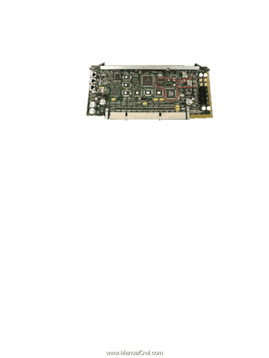
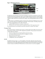
UGUY Every cabinet contains one UGUY. See (Figure 1-3). The UGUY plugs into the HUCB. It is not hot-swappable. Its MP microprocessor controls power monitor functions, executing the Power Monitor 3 (PM3) firmware and the CLU firmware. Figure 1-3 UGUY CLU Functionality The CLU collects and reports the configuration information for itself, the main backplane, I/O backplanes, and the SUB/HUB. Each of these boards has a configuration EEPROM containing FRU IDs, revision information, and for the main backplane and I/O backplanes, maximum power requirements in the fully configured, fully loaded states. These EEPROMs are powered by housekeeping power (HKP) and are accessible to SARG from an I2C bus. The power requirement information is sent to the PM3 automatically when HKP is applied or when a new entity is plugged in. The configuration information is sent to the SUB in response to a get_config command. The CLU gathers the following information over its five I2C buses: • Board revision information is contained in the board's configuration EEPROM for the UGUY board, the SBCH board, the main backplane, the main backplane power boards (HBPB), the I/O backplane (HIOB), and the I/O backplane power boards (IOPB). • Power requirements from the configuration EEPROM for the main backplane (HLSB or HRSB) and the I/O backplanes. This information is sent to the PM3 processor so it can calculate cabinet power requirements. • Power control and status interface. Another function of the UGUY is to use the power_ good signals to drive the power on sequence. • Reset control which includes a reset for each I/O backplane, a main backplane cabinet reset, TRST - JTAG reset for all JTAG scan chains in the entire cabinet, a system clock control margin control, nominal or high margin and a clock source selection and internal or external OL* LED control. • Status LEDs for the SBA cable OL*, the cell OL*, the I/O backplane OL*, the JTAG scan control, the three scan chains per cell, the three scan chains per I/O backplane, and the three scan chains on the main backplane. PM3 Functionality The PM3 performs the following functions: Utilities Subsystem 23
-
 1
1 -
2
-
3
-
4
-
5
-
6
-
7
-
8
-
9
-
10
-
11
-
12
-
13
-
14
-
15
-
16
-
17
-
 18
18 -
 19
19 -
 20
20 -
 21
21 -
 22
22 -
 23
23 -
 24
24 -
 25
25 -
 26
26 -
 27
27 -
 28
28 -
29
-
30
-
31
-
32
-
33
-
34
-
35
-
36
-
37
-
38
-
39
-
40
-
41
-
42
-
43
-
44
-
45
-
46
-
47
-
48
-
49
-
50
-
51
-
52
-
53
-
54
-
55
-
56
-
57
-
58
-
59
-
60
-
61
-
62
-
63
-
64
-
65
-
66
-
67
-
68
-
69
-
70
-
71
-
72
-
73
-
74
-
75
-
76
-
77
-
78
-
79
-
80
-
81
-
82
-
83
-
84
-
85
-
86
-
87
-
88
-
89
-
90
-
91
-
92
-
93
-
94
-
95
-
96
-
97
-
98
-
99
-
100
-
101
-
102
-
103
-
104
-
105
-
106
-
107
-
108
-
109
-
110
-
111
-
112
-
113
-
114
-
115
-
116
-
117
-
118
-
119
-
120
-
121
-
122
-
123
-
124
-
125
-
126
-
127
-
128
-
129
-
130
-
131
-
132
-
133
-
134
-
135
-
136
-
137
-
138
-
139
-
140
-
141
-
142
-
143
-
144
-
145
-
146
-
147
-
148
-
149
-
150
-
151
-
152
-
153
-
154
-
155
-
156
-
157
-
158
-
159
-
160
-
161
-
162
-
163
-
164
-
165
-
166
-
167
-
168
-
169
-
170
-
171
-
172
-
173
-
174
-
175
-
176
-
177
-
178
-
179
-
180
-
181
-
182
-
183
-
184
-
185
-
186
-
187
-
188
-
189
-
190
-
191
-
192
-
193
-
194
-
195
-
196
-
197
-
198
-
199
-
200
 |
 |