HP Superdome SX2000 User Service Guide, Seventh Edition - HP Integrity Superdo - Page 86
A 5-Wire Connector, WARNING, Installing the PDCA
 |
View all HP Superdome SX2000 manuals
Add to My Manuals
Save this manual to your list of manuals |
Page 86 highlights
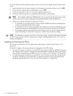
Figure 3-27 A 5-Wire Connector To install the PDCA, follow these steps: WARNING! Make sure the circuit breaker on the PDCA is OFF. 1. Remove the rear PDCA bezel by removing the four retaining screws. 2. Run the power cord down through the appropriate opening in the floor tile. 3. Insert the PDCA into its slot (Figure 3-28 (page 86)). Figure 3-28 Installing the PDCA 4. Using a T-20 driver, attach the four screws that hold the PDCA in place. 5. If required, repeat step 2 through step 4 for the second PDCA. 86 Installing the System
-
 1
1 -
2
-
3
-
4
-
5
-
6
-
7
-
8
-
9
-
10
-
11
-
12
-
13
-
14
-
15
-
16
-
17
-
18
-
19
-
20
-
21
-
22
-
23
-
24
-
25
-
26
-
27
-
28
-
29
-
30
-
31
-
32
-
33
-
34
-
35
-
36
-
37
-
38
-
39
-
40
-
41
-
42
-
43
-
44
-
45
-
46
-
47
-
48
-
49
-
50
-
51
-
52
-
53
-
54
-
55
-
56
-
57
-
58
-
59
-
60
-
61
-
62
-
63
-
64
-
65
-
66
-
67
-
68
-
69
-
70
-
71
-
72
-
73
-
74
-
75
-
76
-
77
-
78
-
79
-
80
-
 81
81 -
 82
82 -
 83
83 -
 84
84 -
 85
85 -
 86
86 -
 87
87 -
 88
88 -
 89
89 -
 90
90 -
 91
91 -
92
-
93
-
94
-
95
-
96
-
97
-
98
-
99
-
100
-
101
-
102
-
103
-
104
-
105
-
106
-
107
-
108
-
109
-
110
-
111
-
112
-
113
-
114
-
115
-
116
-
117
-
118
-
119
-
120
-
121
-
122
-
123
-
124
-
125
-
126
-
127
-
128
-
129
-
130
-
131
-
132
-
133
-
134
-
135
-
136
-
137
-
138
-
139
-
140
-
141
-
142
-
143
-
144
-
145
-
146
-
147
-
148
-
149
-
150
-
151
-
152
-
153
-
154
-
155
-
156
-
157
-
158
-
159
-
160
-
161
-
162
-
163
-
164
-
165
-
166
-
167
-
168
-
169
-
170
-
171
-
172
-
173
-
174
-
175
-
176
-
177
-
178
-
179
-
180
-
181
-
182
-
183
-
184
-
185
-
186
-
187
-
188
-
189
-
190
-
191
-
192
-
193
-
194
-
195
-
196
-
197
-
198
-
199
-
200
 |
 |
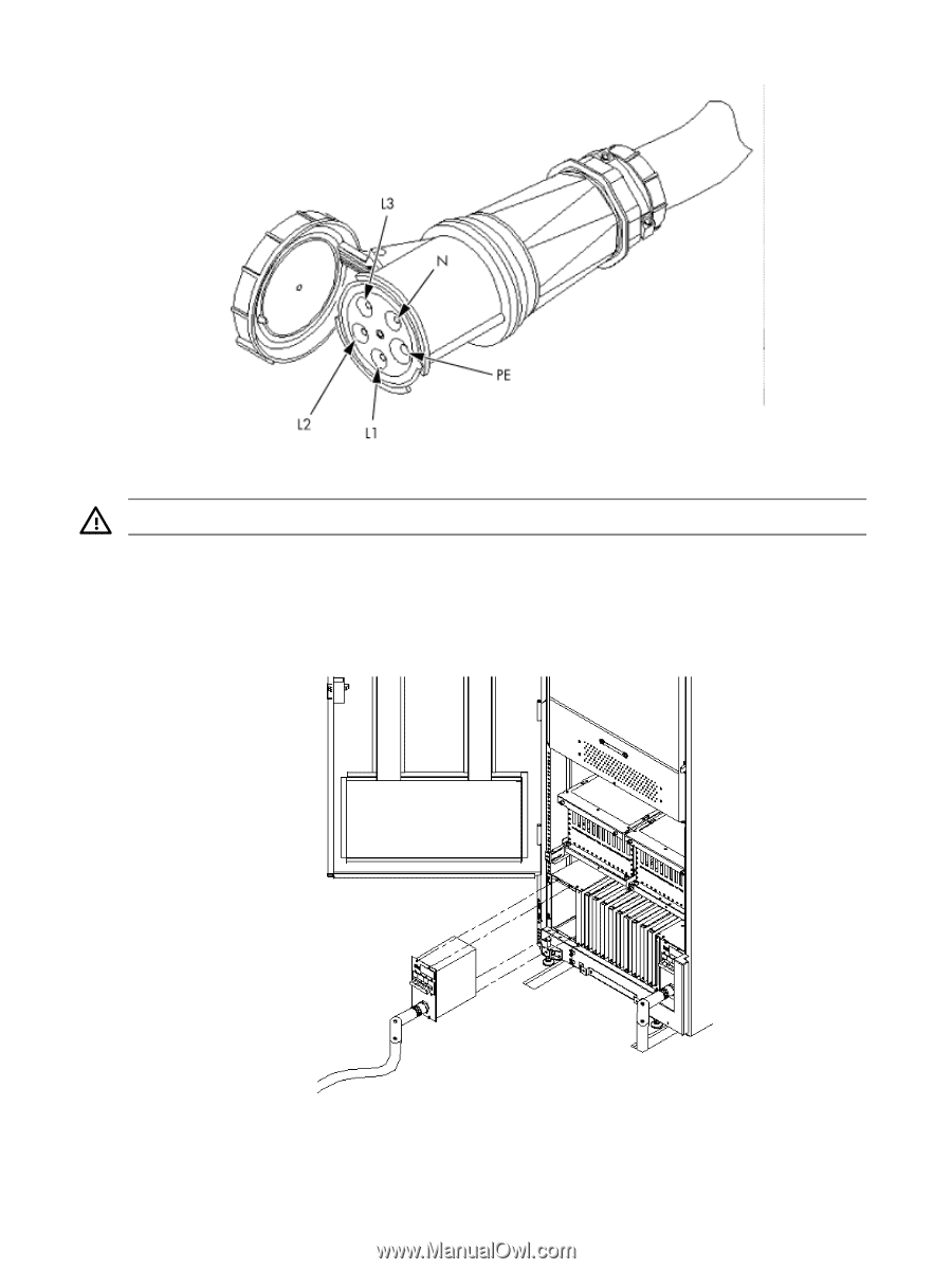
Figure 3-27 A 5-Wire Connector
To install the PDCA, follow these steps:
WARNING!
Make sure the circuit breaker on the PDCA is
OFF
.
1.
Remove the rear PDCA bezel by removing the four retaining screws.
2.
Run the power cord down through the appropriate opening in the floor tile.
3.
Insert the PDCA into its slot (
Figure 3-28 (page 86)
).
Figure 3-28 Installing the PDCA
4.
Using a T-20 driver, attach the four screws that hold the PDCA in place.
5.
If required, repeat step 2 through step 4 for the second PDCA.
86
Installing the System