Intel S1200BTL Product Specification - Page 102
Connector/Header Locations and Pin-outs - front panel connector
 |
View all Intel S1200BTL manuals
Add to My Manuals
Save this manual to your list of manuals |
Page 102 highlights
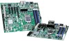
Connector/Header Locations and Pin-outs Intel®Server Board S1200BT TPS 7. Connector/Header Locations and Pin-outs 7.1 Board Connector Information The following section provides detailed information regarding all connectors, headers, and jumpers on the server board. It lists all connector types available on the board and the corresponding reference designators printed on the silkscreen. Table 17. Board Connector Matrix on S1200BTL Connector Quantity Reference Designators Connector Type Power supply 3 CPU 1 Main memory 4 Intel® RMM4 Lite 1 Intel® RMM4 1 Dedicated NIC SAS Module 1 CPU Fan 1 System Fans 4 Battery 1 NIC/Stack 2x USB 2 Video 1 Serial port A 1 Serial port B 1 Front panel 1 Dual- USB Internal 2 Header PCI-E x16 1 PCI-E x8 3 PCI 32 1 Chassis Intrusion 1 6Gb/s Serial ATA 2 3Gb/s Serial ATA 4 IPMB 1 HSBP 1 Smart Module 1 SATA RAID key 1 SATA_SGPIO 1 J9G1, J9A1, J9F1 J7D1 J8H1, J8H2, J8H3, J9H1 J4B1 J5C1 J2H1 J5J1 J1J4, J5J2, J7J1, J7B1 BT5B1 J5A1, J6A1 J7A1 J8A1 J1B2 J1C1 J1D1, J1E1 J4B3 J2B2, J3B1, J4B2 J1B1 J4A1 J1H1,J1H3 J1H4, J1H2, J1G1, J1F4 J1H5 J1J2 J3F2 J4A3 J1J3 Main power CPU power P/S aux CPU sockets DIMM sockets Header Header Header Header Header Battery holder Dual USB External DSub Connector Header Header Header Card Edge Card Edge Card Edge Header Header Header Header Header Header Header Header Pin Count 24 8 5 1155 240 8 30 50 4 4 3 8 15 9 9 24 10 164 98 120 2 7 7 4 4 10 4 4 90 Revision 1.0 Intel order number G13326-003
-
 1
1 -
2
-
3
-
4
-
5
-
6
-
7
-
8
-
9
-
10
-
11
-
12
-
13
-
14
-
15
-
16
-
17
-
18
-
19
-
20
-
21
-
22
-
23
-
24
-
25
-
26
-
27
-
28
-
29
-
30
-
31
-
32
-
33
-
34
-
35
-
36
-
37
-
38
-
39
-
40
-
41
-
42
-
43
-
44
-
45
-
46
-
47
-
48
-
49
-
50
-
51
-
52
-
53
-
54
-
55
-
56
-
57
-
58
-
59
-
60
-
61
-
62
-
63
-
64
-
65
-
66
-
67
-
68
-
69
-
70
-
71
-
72
-
73
-
74
-
75
-
76
-
77
-
78
-
79
-
80
-
81
-
82
-
83
-
84
-
85
-
86
-
87
-
88
-
89
-
90
-
91
-
92
-
93
-
94
-
95
-
96
-
 97
97 -
 98
98 -
 99
99 -
 100
100 -
 101
101 -
 102
102 -
 103
103 -
 104
104 -
 105
105 -
 106
106 -
 107
107 -
108
-
109
-
110
-
111
-
112
-
113
-
114
-
115
-
116
-
117
-
118
-
119
-
120
-
121
-
122
-
123
-
124
-
125
-
126
-
127
-
128
-
129
-
130
-
131
-
132
-
133
-
134
-
135
-
136
-
137
-
138
-
139
-
140
-
141
-
142
-
143
-
144
-
145
-
146
-
147
-
148
-
149
-
150
-
151
-
152
-
153
 |
 |
