Intel S1200BTL Product Specification - Page 129
Residual Voltage Immunity in Standby Mode, Protection Circuits
 |
View all Intel S1200BTL manuals
Add to My Manuals
Save this manual to your list of manuals |
Page 129 highlights
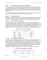
Intel®Server Board S1200BT TPS Design and Environmental Specifications 10.3.11 Residual Voltage Immunity in Standby Mode The power supply is immune to any residual voltage placed on its outputs (typically, a leakage voltage through the system from standby output) up to 500 mV. There is no additional heat generated nor stressing of any internal components with this voltage applied to any individual output and all outputs simultaneously. It also does not trip the power supply protection circuits during turn on. The residual voltage at the power supply outputs for a no-load condition does not exceed 100 mV when AC voltage is applied and the PSON# signal is de-asserted. 10.3.12 Protection Circuits Protection circuits inside the power supply should cause only the power supply's main outputs to shut down. If the power supply latches off due to a protection circuit tripping, an AC cycle OFF for 15 seconds and a PSON# cycle HIGH for 1 second should reset the power supply. 10.3.12.1 Over-current Protection (OCP) The power supply has current limits to prevent the +3.3 V, +5 V, and +12 V outputs from exceeding the values shown in the following table. If the current limits are exceeded, the power supply shuts down and latches off. The latch is cleared by toggling the PSON# signal or using an AC power interruption. The power supply is not damaged from repeated power cycling in this condition. -12 V and 5 VSB are protected under over-current or shorted conditions so no damage can occur to the power supply. Auto-recovery feature is a requirement on 5 VSB rail. Table 54. Over-Current Protection (OCP) VOLTAGE +3.3V +5V +12V -12V 5VSB 15A 20A 30A 0.625A N/A OVER CURRENT LIMIT Min Max 21A 27A 40A 2A 4A 10.3.12.2 Over-Voltage Protection (OVP) The power supply over-voltage protection is locally sensed. The power supply shuts down and latches off after an over-voltage condition occurs. You can clear this latch by toggling the PSON# signal or using an AC power interruption. The following table contains the over-voltage limits. The values are measured at the output of the power supply's connectors. The voltage never exceeds the maximum levels when measured at the power pins of the power supply connector during any single point of fail. The voltage never trips any lower than the minimum levels when measured at the power pins of the power supply connector. Exception: +5 VSB rail should be able to recover after an over-voltage condition occurs. Table 55. Over-voltage Protection (OVP) Limits Output Voltage +3.3 V +5 V +12 V Minimum (V) 3.9 5.7 13.3 Maximum (V) 4.5 6.2 14.5 Revision 1.0 117 Intel order number G13326-003
-
 1
1 -
2
-
3
-
4
-
5
-
6
-
7
-
8
-
9
-
10
-
11
-
12
-
13
-
14
-
15
-
16
-
17
-
18
-
19
-
20
-
21
-
22
-
23
-
24
-
25
-
26
-
27
-
28
-
29
-
30
-
31
-
32
-
33
-
34
-
35
-
36
-
37
-
38
-
39
-
40
-
41
-
42
-
43
-
44
-
45
-
46
-
47
-
48
-
49
-
50
-
51
-
52
-
53
-
54
-
55
-
56
-
57
-
58
-
59
-
60
-
61
-
62
-
63
-
64
-
65
-
66
-
67
-
68
-
69
-
70
-
71
-
72
-
73
-
74
-
75
-
76
-
77
-
78
-
79
-
80
-
81
-
82
-
83
-
84
-
85
-
86
-
87
-
88
-
89
-
90
-
91
-
92
-
93
-
94
-
95
-
96
-
97
-
98
-
99
-
100
-
101
-
102
-
103
-
104
-
105
-
106
-
107
-
108
-
109
-
110
-
111
-
112
-
113
-
114
-
115
-
116
-
117
-
118
-
119
-
120
-
121
-
122
-
123
-
 124
124 -
 125
125 -
 126
126 -
 127
127 -
 128
128 -
 129
129 -
 130
130 -
 131
131 -
 132
132 -
 133
133 -
 134
134 -
135
-
136
-
137
-
138
-
139
-
140
-
141
-
142
-
143
-
144
-
145
-
146
-
147
-
148
-
149
-
150
-
151
-
152
-
153
 |
 |
