Intel S1200BTL Product Specification - Page 44
Platform Management, Intel®, Server Board S1200BT TPS, Revision 1.0, Intel order number G13326-003 - front panel connections
 |
View all Intel S1200BTL manuals
Add to My Manuals
Save this manual to your list of manuals |
Page 44 highlights
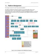
Platform Management Intel®Server Board S1200BT TPS 4. Platform Management This chapter is only for The Intel® Server Board S1200BTL. The platform management subsystem is based on the Integrated BMC features of the ServerEngines* Pilot III. The onboard platform management subsystem consists of communication buses, sensors, system BIOS, and server management firmware. The following diagram provides an overview of the Server Management Bus (SMBUS) architecture used on this server board. MM[0] IPMB (3.3V STBY) Voltage Translation IPMB (5V STBY) M/S IPMB Connector MM[1] MM[2] Sensor (3.3V STBY) S S BB sensor2 Front-Panel S Front-Panel S BB Sensor1 Temp: 0x98 FRU: 0xAE Temp: 0x9E Temp: 0x9A PCI (3.3V STBY) S PCI/PCIe Slots Note: The SMBus to PCIE slot connection is reserved for certain cased which will use it for GPU management. S BB Sensor3 Temp: 0x9C MM[3] Host (3.3V STBY) ISOLATION Host (3.3V Main) S BB Sensor4 Temp: 0x96 S BB Optional sensor 5 Temp: 0x94 S LCP 0x22 Note: This sensor5 address is optional only reserved for possible Thermal management on certain board such as IronPass IBMC S CK-MNG 0xD0 Nuvoton LOT6 0x6C S CK420BQ 0xD2 S DB1900Z 0xD8 MM XDP 0 N/A MM XDP 1 N/A MM[4] SMLink0 @ 400kHz (3.3V STBY) S Lewsville 0xC8 (Bromollow) MM[5] HSBP (3.3V STBY) ISOLATION MM[6] S HSBP1 PSOC 0xD0 Temp: 0x90 FRU: 0xA0 S HSBP2 PSOC 0xD6 Temp: 0x96 FRU: 0xA6 MM/S[7] S Riser1 FRU: 0xA0 Temp: 0x90 S Riser2 FRU: 0xA2 Temp: 0x92 S rIOM FRU: 0xA4 Temp: 0x94 S SAS Module FRU: 0xA6 Temp: 0x96 PMBus (3.3V STBY) 0-Ω STUFFED S PMBus PS 0 FRU: 0xA0 / Device: 0xB0 S PMBus PS 1 FRU: 0xA2 / Device: 0xB2 S HSBP3 PSOC 0xD4 Temp: 0x94 FRU: 0xA4 SMLink1 @ 100kHz (3.3V STBY) M/S PCH 0x88 (0x88 is default for SSB) MM[0] ME 0xTBD MM/S[1] 0xTBD PATSBURG -A/D S SMBus Slave (Main) M/S SMBus Master (Main) MM SMBus Multi-Master (Main) MM/S SMBus Multi-Master (Standby) S SMBus Slave (Standby) Figure 14. Server Management Bus (SMBUS) Block Diagram 32 Revision 1.0 Intel order number G13326-003
-
 1
1 -
2
-
3
-
4
-
5
-
6
-
7
-
8
-
9
-
10
-
11
-
12
-
13
-
14
-
15
-
16
-
17
-
18
-
19
-
20
-
21
-
22
-
23
-
24
-
25
-
26
-
27
-
28
-
29
-
30
-
31
-
32
-
33
-
34
-
35
-
36
-
37
-
38
-
 39
39 -
 40
40 -
 41
41 -
 42
42 -
 43
43 -
 44
44 -
 45
45 -
 46
46 -
 47
47 -
 48
48 -
 49
49 -
50
-
51
-
52
-
53
-
54
-
55
-
56
-
57
-
58
-
59
-
60
-
61
-
62
-
63
-
64
-
65
-
66
-
67
-
68
-
69
-
70
-
71
-
72
-
73
-
74
-
75
-
76
-
77
-
78
-
79
-
80
-
81
-
82
-
83
-
84
-
85
-
86
-
87
-
88
-
89
-
90
-
91
-
92
-
93
-
94
-
95
-
96
-
97
-
98
-
99
-
100
-
101
-
102
-
103
-
104
-
105
-
106
-
107
-
108
-
109
-
110
-
111
-
112
-
113
-
114
-
115
-
116
-
117
-
118
-
119
-
120
-
121
-
122
-
123
-
124
-
125
-
126
-
127
-
128
-
129
-
130
-
131
-
132
-
133
-
134
-
135
-
136
-
137
-
138
-
139
-
140
-
141
-
142
-
143
-
144
-
145
-
146
-
147
-
148
-
149
-
150
-
151
-
152
-
153
 |
 |
