Intel S1200BTL Product Specification - Page 121
Intel, Light Guided Diagnostics - boot issue
 |
View all Intel S1200BTL manuals
Add to My Manuals
Save this manual to your list of manuals |
Page 121 highlights
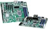
Intel®Server Board S1200BT TPS Intel®Light Guided Diagnostics 9. Intel® Light Guided Diagnostics The server board has several on-board diagnostic LEDs to assist in troubleshooting board-level issues. This section shows where each LED is located on the server board and describes the function of each LED. 9.1 System Status LED (Only for S1200BTL) The server board provides a system status indicator LED on the front panel. This indicator LED has specific states and corresponding interpretation as shown in the following table: LED Power/Sleep Status Global HDD Activity LAN 1-2 Chassis Identification Table 44. Front Panel LED Behavior Summary Color Green Green Green Green Amber Amber Green Green Green Blue Blue Condition On Blink Off On Blink On Blink Off Blink Off On Blink Off On Blink Off Description Power on or S0 sleep S1 sleep or S3 standby only for workstation baseboards Off (also sleep S4/S5 modes) System ready/No alarm System ready, but degraded: redundancy lost such as PS or fan failure; non-critical temp/voltage threshold; battery failure; or predictive PS failure. Critical alarm: Voltage, thermal, or power fault; CPU missing; insufficient power unit redundancy resource offset asserted Non-Critical failure: Critical temp/voltage threshold; VDR hot asserted; min number fans not present or failed AC power off: System unplugged AC power on: System powered off and in standby, no prior degraded\non-critical\critical state HDD access No access and no fault LAN link/ no access LAN access Idle Front panel chassis ID button pressed Unit selected for identification via software No identification 9.2 Post Code Diagnostic LEDs During the system boot process, the BIOS executes several platform configuration processes, each of which is assigned a specific hex POST code number. As each configuration routine is started, the BIOS displays the POST code on the POST code diagnostic LEDs found on the back edge of the server board. To assist in troubleshooting a system hang during the POST process, the diagnostic LEDs can be used to identify the last POST process executed. Revision 1.0 109 Intel order number G13326-003
-
 1
1 -
2
-
3
-
4
-
5
-
6
-
7
-
8
-
9
-
10
-
11
-
12
-
13
-
14
-
15
-
16
-
17
-
18
-
19
-
20
-
21
-
22
-
23
-
24
-
25
-
26
-
27
-
28
-
29
-
30
-
31
-
32
-
33
-
34
-
35
-
36
-
37
-
38
-
39
-
40
-
41
-
42
-
43
-
44
-
45
-
46
-
47
-
48
-
49
-
50
-
51
-
52
-
53
-
54
-
55
-
56
-
57
-
58
-
59
-
60
-
61
-
62
-
63
-
64
-
65
-
66
-
67
-
68
-
69
-
70
-
71
-
72
-
73
-
74
-
75
-
76
-
77
-
78
-
79
-
80
-
81
-
82
-
83
-
84
-
85
-
86
-
87
-
88
-
89
-
90
-
91
-
92
-
93
-
94
-
95
-
96
-
97
-
98
-
99
-
100
-
101
-
102
-
103
-
104
-
105
-
106
-
107
-
108
-
109
-
110
-
111
-
112
-
113
-
114
-
115
-
 116
116 -
 117
117 -
 118
118 -
 119
119 -
 120
120 -
 121
121 -
 122
122 -
 123
123 -
 124
124 -
 125
125 -
 126
126 -
127
-
128
-
129
-
130
-
131
-
132
-
133
-
134
-
135
-
136
-
137
-
138
-
139
-
140
-
141
-
142
-
143
-
144
-
145
-
146
-
147
-
148
-
149
-
150
-
151
-
152
-
153
 |
 |
