Intel S1200BTL Product Specification - Page 109
SAS Connectors
 |
View all Intel S1200BTL manuals
Add to My Manuals
Save this manual to your list of manuals |
Page 109 highlights
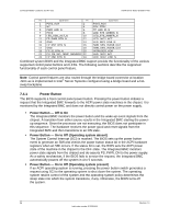
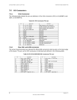
Intel®Server Board S1200BT TPS Connector/Header Locations and Pin-outs Table 30. RJ-45 10/100/1000 NIC Connector Pin-out (J6A1) Pin 1 3 5 7 9 11 13 15 17 19 21 Signal Name P5V_USB_PWR75 USB_PCH_11_FB_DP P5V_USB_PWR75 USB_PCH_10_FB_DP P1V8_PHY_VCT_R NIC1_MDIN NIC1_MDIN NIC1_MDIN NIC1_MDIN LED_NIC1_LINK_ACT_0_R LED_NIC1_2 Pin Signal Name 2 USB_PCH_11_FB_DN 4 GND 6 USB_PCH_10_FB_DN 8 GND 10 NIC1_MDIP 12 NIC1_MDIP 14 NIC2_MDIP 16 NIC2_MDIP 18 GND 20 P3V3_AUX 22 LED_NIC1_LINK1000_1 7.5.3 SATA The sever board provides up to two 6Gb/s SATA connectors and four 3Gb/s SATA connectors. The pin configuration for each connector is identical and defined in the following table: Table 31. 6Gb/s SATA Connector Pin-Out Pin Signal Name 1 GND 2 SATA_TX_P 3 SATA_TX_N 4 GND 5 SATA_RX_N 6 SATA_RX_P 7 GND Table 32. 3Gb/s SATA Connector Pin-out Pin Signal Name 1 GND 2 SATA/SAS_TX_P_C 3 SATA/SAS_TX_N_C 4 GND 5 SATA/SAS_RX_N_C 6 SATA/SAS_RX_P_C 7 GND Description Ground Positive side of transmit differential pair Negative side of transmit differential pair Ground Negative side of receive differential pair Positive side of receive differential pair Ground 7.5.4 SAS Connectors The Intel® Server Board S1200BTL provides one SAS connector. The pin configuration is identical and defined in the following table: Revision 1.0 97 Intel order number G13326-003
-
 1
1 -
2
-
3
-
4
-
5
-
6
-
7
-
8
-
9
-
10
-
11
-
12
-
13
-
14
-
15
-
16
-
17
-
18
-
19
-
20
-
21
-
22
-
23
-
24
-
25
-
26
-
27
-
28
-
29
-
30
-
31
-
32
-
33
-
34
-
35
-
36
-
37
-
38
-
39
-
40
-
41
-
42
-
43
-
44
-
45
-
46
-
47
-
48
-
49
-
50
-
51
-
52
-
53
-
54
-
55
-
56
-
57
-
58
-
59
-
60
-
61
-
62
-
63
-
64
-
65
-
66
-
67
-
68
-
69
-
70
-
71
-
72
-
73
-
74
-
75
-
76
-
77
-
78
-
79
-
80
-
81
-
82
-
83
-
84
-
85
-
86
-
87
-
88
-
89
-
90
-
91
-
92
-
93
-
94
-
95
-
96
-
97
-
98
-
99
-
100
-
101
-
102
-
103
-
 104
104 -
 105
105 -
 106
106 -
 107
107 -
 108
108 -
 109
109 -
 110
110 -
 111
111 -
 112
112 -
 113
113 -
 114
114 -
115
-
116
-
117
-
118
-
119
-
120
-
121
-
122
-
123
-
124
-
125
-
126
-
127
-
128
-
129
-
130
-
131
-
132
-
133
-
134
-
135
-
136
-
137
-
138
-
139
-
140
-
141
-
142
-
143
-
144
-
145
-
146
-
147
-
148
-
149
-
150
-
151
-
152
-
153
 |
 |
