Intel S1200BTL Product Specification - Page 105
Front Control Panel Connector
 |
View all Intel S1200BTL manuals
Add to My Manuals
Save this manual to your list of manuals |
Page 105 highlights
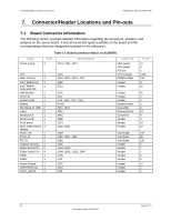
Intel®Server Board S1200BT TPS Connector/Header Locations and Pin-outs 7.3.2 7.3.3 Pin Name 17 GND 19 GND 21 GND 23 GND 25 GND 27 GND 29 GND LPC/IPMB Header Pin Name 18 RXD_0 20 RXD_1 22 RXD_2 24 RXD_3 26 TX_CLK 28 RX_CLK 30 PRESENT# Table 23. LPC/IPMB Header Pin-out (J1H5) Pin Signal Name 1 SMB_IPMB_5VSB_DAT 2 GND 3 SMB_IPMB_5VSB_CLK 4 P5V_STBY HSBP Header Description Integrated BMC IMB 5V standby data line Ground Integrated BMC IMB 5V standby clock line +5 V standby power 7.3.4 Table 24. HSBP Header Pin-out (J1J2) Pin Signal Name 1 SMB_HSBP_5V_DAT 2 GND 3 SMB_HSBP_5V_CLK 4 FM_HSBP_ADD_C2 SGPIO Header Table 25. SGPIO Header Pin-out (J1J3 on S1200BTL and J2J2 on S1200BTS) Pin Signal Name 1 SGPIO_CLOCK 2 SGPIO_LOAD 3 GND 4 SGPIO_DATAOUT0 5 SGPIO_DATAOUT1 Description SGPIO Clock Signal SGPIO Load Signal SGPIO Data Out SGPIO Data In 7.4 Front Control Panel Connector The server board provides a 24-pin SSI front panel connector (J1C1) for use with Intel® and third-party chassis. The following table provides the pin-out for this connector. Table 26. Front Panel SSI Standard 24-pin Connector Pin-out (J1C1 on S1200BTL or J1C2 on S1200BTS) Revision 1.0 93 Intel order number G13326-003
-
 1
1 -
2
-
3
-
4
-
5
-
6
-
7
-
8
-
9
-
10
-
11
-
12
-
13
-
14
-
15
-
16
-
17
-
18
-
19
-
20
-
21
-
22
-
23
-
24
-
25
-
26
-
27
-
28
-
29
-
30
-
31
-
32
-
33
-
34
-
35
-
36
-
37
-
38
-
39
-
40
-
41
-
42
-
43
-
44
-
45
-
46
-
47
-
48
-
49
-
50
-
51
-
52
-
53
-
54
-
55
-
56
-
57
-
58
-
59
-
60
-
61
-
62
-
63
-
64
-
65
-
66
-
67
-
68
-
69
-
70
-
71
-
72
-
73
-
74
-
75
-
76
-
77
-
78
-
79
-
80
-
81
-
82
-
83
-
84
-
85
-
86
-
87
-
88
-
89
-
90
-
91
-
92
-
93
-
94
-
95
-
96
-
97
-
98
-
99
-
 100
100 -
 101
101 -
 102
102 -
 103
103 -
 104
104 -
 105
105 -
 106
106 -
 107
107 -
 108
108 -
 109
109 -
 110
110 -
111
-
112
-
113
-
114
-
115
-
116
-
117
-
118
-
119
-
120
-
121
-
122
-
123
-
124
-
125
-
126
-
127
-
128
-
129
-
130
-
131
-
132
-
133
-
134
-
135
-
136
-
137
-
138
-
139
-
140
-
141
-
142
-
143
-
144
-
145
-
146
-
147
-
148
-
149
-
150
-
151
-
152
-
153
 |
 |
