Intel S1200BTL Product Specification - Page 106
Power Button
 |
View all Intel S1200BTL manuals
Add to My Manuals
Save this manual to your list of manuals |
Page 106 highlights
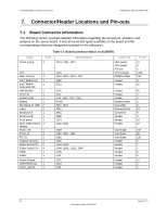
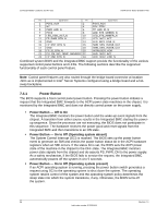
Connector/Header Locations and Pin-outs Intel®Server Board S1200BT TPS Pin Signal Name Pin Signal Name 1 P3V3_AUX 2 3 NC 4 5 PWR_LED_N 6 7 P3V3 8 9 LED_HDD_ACT_N 10 11 FP_PWR_BTN_N 12 13 GND 14 15 FP_RST_BTN_N 16 17 GND 18 19 FP_ID_BTN_N 20 21 PU_FM_SIO_TEMP_SENSOR 22 23 FP_NMI_BTN_N 24 P3V3_AUX P5V_STBY TP_LED_ID_N LED_STS_GREEN_N LED_STS_AMBER_N LED_ NIC1_ACT LED_NIC1_LINK_N SMB_SEN_3V3SB_DAT SMB_SEN_3V3SB_CLK INTRUDER_HDR LED_ NIC2_ACT LED_ NIC2_LINK_N Combined system BIOS and the Integrated BMC support provide the functionality of the various supported control panel buttons and LEDs. The following sections describe the supported functionality of each control panel feature. Note: Control panel features are also routed through the bridge board connector at location J1C1 as is implemented in Intel® Server Systems configured using a bridge board and a hot- swap backplane. 7.4.1 Power Button The BIOS supports a front control panel power button. Pressing the power button initiates a request that the Integrated BMC forwards to the ACPI power state machines in the chipset. It is monitored by the Integrated BMC and does not directly control power on the power supply. Power Button - Off to On The Integrated BMC monitors the power button and the wake-up event signals from the chipset. A transition from either source results in the Integrated BMC starting the powerup sequence. Since the processor are not executing, the BIOS does not participate in this sequence. The hardware receives the power good and reset signals from the Integrated BMC and then transitions to an ON state. Power Button - On to Off (Operating system absent) The System Control Interrupt (SCI) is masked. The BIOS sets up the power button event to generate an SMI and checks the power button status bit in the ACPI hardware registers when an SMI occurs. If the status bit is set, the BIOS sets the ACPI power state of the machine in the chipset to the OFF state. The Integrated BMC monitors power state signals from the chipset and de-asserts PS_PWR_ON to the power supply. As a safety mechanism, if the BIOS fails to service the request, the Integrated BMC automatically powers off the system in 4 to 5 seconds. Power Button - On to Off (Operating system present) If an ACPI operating system is running, pressing the power button switch generates a request using SCI to the operating system to shut down the system. The operating system retains control of the system and the operating system policy determines the sleep state into which the system transitions, if any. Otherwise, the BIOS turns off the system. 94 Revision 1.0 Intel order number G13326-003
-
 1
1 -
2
-
3
-
4
-
5
-
6
-
7
-
8
-
9
-
10
-
11
-
12
-
13
-
14
-
15
-
16
-
17
-
18
-
19
-
20
-
21
-
22
-
23
-
24
-
25
-
26
-
27
-
28
-
29
-
30
-
31
-
32
-
33
-
34
-
35
-
36
-
37
-
38
-
39
-
40
-
41
-
42
-
43
-
44
-
45
-
46
-
47
-
48
-
49
-
50
-
51
-
52
-
53
-
54
-
55
-
56
-
57
-
58
-
59
-
60
-
61
-
62
-
63
-
64
-
65
-
66
-
67
-
68
-
69
-
70
-
71
-
72
-
73
-
74
-
75
-
76
-
77
-
78
-
79
-
80
-
81
-
82
-
83
-
84
-
85
-
86
-
87
-
88
-
89
-
90
-
91
-
92
-
93
-
94
-
95
-
96
-
97
-
98
-
99
-
100
-
 101
101 -
 102
102 -
 103
103 -
 104
104 -
 105
105 -
 106
106 -
 107
107 -
 108
108 -
 109
109 -
 110
110 -
 111
111 -
112
-
113
-
114
-
115
-
116
-
117
-
118
-
119
-
120
-
121
-
122
-
123
-
124
-
125
-
126
-
127
-
128
-
129
-
130
-
131
-
132
-
133
-
134
-
135
-
136
-
137
-
138
-
139
-
140
-
141
-
142
-
143
-
144
-
145
-
146
-
147
-
148
-
149
-
150
-
151
-
152
-
153
 |
 |
