Intel S1200BTL Product Specification - Page 8

List of s - manual

Page 8 highlights

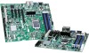
List of Figures Intel®Server Board S1200BT TPS List of Figures Figure 1. Intel® Server Board S1200BTL Picture 4 Figure 2. Intel® Server Board S1200BTS Picture 5 Figure 3. Intel® Server Board S1200BTL Layout 6 Figure 4. Intel® Server Board S1200BTS Layout 7 Figure 5. Intel® Server Board S1200BTL - Hole and Component Positions 9 Figure 6. Intel® Server Board S1200BTL - Major Connector Pin Location (1 of 2 10 Figure 7. Intel® Server Board S1200BTL - Major Connector Pin Location (2 of 2 11 Figure 8. Intel® Server Board S1200BTL - Primary Side Keepout Zone 12 Figure 9. Intel® Server Board S1200BTL - Secondary Side Keepout Zone 13 Figure 10. Intel® Server Board S1200BT Rear I/O Layout 14 Figure 11. Intel® Server Board S1200BTL Functional Block Diagram 15 Figure 12. Intel® Server Board S1200BTS Functional Block Diagram 16 Figure 13. Integrated BMC Hardware 26 Figure 14. Server Management Bus (SMBUS) Block Diagram 32 Figure 15. Main Screen...56 Figure 16. Advanced Screen...59 Figure 17. Processor Configuration Screen 62 Figure 18. Memory Configuration Screen 68 Figure 19. Mass Storage Controller Configuration Screen 71 Figure 20. Serial Port Configuration Screen 72 Figure 21. USB Configuration Screen 73 Figure 22. PCI Configuration Screen 74 Figure 23. System Acoustic and Performance Configuration 75 Figure 24. Security Screen...75 Figure 25. Server Management Screen (S1200BTL 76 Figure 26. Server Management Screen (S1200BTS 77 Figure 27. Console Redirection Screen 77 Figure 28. System Information Screen (S1200BTL 78 Figure 29.System Information Screen (S1200BTS 79 Figure 30. BMC LAN Configuration Screen (S1200BTL 80 Figure 31. Hardware Monitor Screen, Auto Fan Control (S1200BTS 81 Figure 32. Hardware Monitor Screen, Manual Fan Control (S1200BTS 81 viii Revision 1.0 Intel order number G13326-003

  • 1
  • 2
  • 3
  • 4
  • 5
  • 6
  • 7
  • 8
  • 9
  • 10
  • 11
  • 12
  • 13
  • 14
  • 15
  • 16
  • 17
  • 18
  • 19
  • 20
  • 21
  • 22
  • 23
  • 24
  • 25
  • 26
  • 27
  • 28
  • 29
  • 30
  • 31
  • 32
  • 33
  • 34
  • 35
  • 36
  • 37
  • 38
  • 39
  • 40
  • 41
  • 42
  • 43
  • 44
  • 45
  • 46
  • 47
  • 48
  • 49
  • 50
  • 51
  • 52
  • 53
  • 54
  • 55
  • 56
  • 57
  • 58
  • 59
  • 60
  • 61
  • 62
  • 63
  • 64
  • 65
  • 66
  • 67
  • 68
  • 69
  • 70
  • 71
  • 72
  • 73
  • 74
  • 75
  • 76
  • 77
  • 78
  • 79
  • 80
  • 81
  • 82
  • 83
  • 84
  • 85
  • 86
  • 87
  • 88
  • 89
  • 90
  • 91
  • 92
  • 93
  • 94
  • 95
  • 96
  • 97
  • 98
  • 99
  • 100
  • 101
  • 102
  • 103
  • 104
  • 105
  • 106
  • 107
  • 108
  • 109
  • 110
  • 111
  • 112
  • 113
  • 114
  • 115
  • 116
  • 117
  • 118
  • 119
  • 120
  • 121
  • 122
  • 123
  • 124
  • 125
  • 126
  • 127
  • 128
  • 129
  • 130
  • 131
  • 132
  • 133
  • 134
  • 135
  • 136
  • 137
  • 138
  • 139
  • 140
  • 141
  • 142
  • 143
  • 144
  • 145
  • 146
  • 147
  • 148
  • 149
  • 150
  • 151
  • 152
  • 153

List of Figures
Intel®
Server Board S1200BT TPS
Revision 1.0
Intel order number G13326-003
viii
List of Figures
Figure 1. Intel
®
Server Board S1200BTL Picture
.........................................................................
4
Figure 2. Intel
®
Server Board S1200BTS Picture
........................................................................
5
Figure 3. Intel
®
Server Board S1200BTL Layout
.........................................................................
6
Figure 4. Intel
®
Server Board S1200BTS Layout
.........................................................................
7
Figure 5. Intel
®
Server Board S1200BTL
Hole and Component Positions
................................
9
Figure 6. Intel
®
Server Board S1200BTL
Major Connector Pin Location (1 of 2)
....................
10
Figure 7. Intel
®
Server Board S1200BTL
Major Connector Pin Location (2 of 2)
....................
11
Figure 8. Intel
®
Server Board S1200BTL
Primary Side Keepout Zone
...................................
12
Figure 9. Intel
®
Server Board S1200BTL
Secondary Side Keepout Zone
...............................
13
Figure 10. Intel
®
Server Board S1200BT Rear I/O Layout
.........................................................
14
Figure 11. Intel
®
Server Board S1200BTL Functional Block Diagram
.......................................
15
Figure 12. Intel
®
Server Board S1200BTS Functional Block Diagram
.......................................
16
Figure 13. Integrated BMC Hardware
.......................................................................................
26
Figure 14. Server Management Bus (SMBUS) Block Diagram
..................................................
32
Figure 15. Main Screen
.............................................................................................................
56
Figure 16. Advanced Screen
.....................................................................................................
59
Figure 17. Processor Configuration Screen
..............................................................................
62
Figure 18. Memory Configuration Screen
..................................................................................
68
Figure 19. Mass Storage Controller Configuration Screen
........................................................
71
Figure 20. Serial Port Configuration Screen
..............................................................................
72
Figure 21. USB Configuration Screen
.......................................................................................
73
Figure 22. PCI Configuration Screen
........................................................................................
74
Figure 23. System Acoustic and Performance Configuration
....................................................
75
Figure 24. Security Screen
........................................................................................................
75
Figure 25. Server Management Screen (S1200BTL)
................................................................
76
Figure 26. Server Management Screen (S1200BTS)
................................................................
77
Figure 27. Console Redirection Screen
.....................................................................................
77
Figure 28. System Information Screen (S1200BTL)
..................................................................
78
Figure 29.System Information Screen (S1200BTS)
..................................................................
79
Figure 30. BMC LAN Configuration Screen (S1200BTL)
...........................................................
80
Figure 31. Hardware Monitor Screen, Auto Fan Control (S1200BTS)
.......................................
81
Figure 32. Hardware Monitor Screen, Manual Fan Control (S1200BTS)
...................................
81