Intel S1200BTL Product Specification - Page 111
USB Connector
 |
View all Intel S1200BTL manuals
Add to My Manuals
Save this manual to your list of manuals |
Page 111 highlights
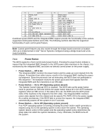
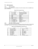
Intel®Server Board S1200BT TPS Connector/Header Locations and Pin-outs 7.5.6 USB Connector There are four external USB ports on two NIC/USB combinations. Section 5.5.2 details the pinout of the connector. Two 2x5 connector on the server board (J1D1, J1E1) provides an option to support an additional USB port, each connector supporting two USB ports. The following table defines the pin-out of the connector. Table 36. Internal USB Connector Pin-out ( J1E1, J1D1) Pin Signal Name 1 USB2_VBUS4 2 USB2_VBUS5 3 USB_ICH_P4N_CONN 4 USB_ICH_P5N_CONN 5 USB_ICH_P4P_CONN 6 USB_ICH_P5P_CONN 7 Ground 8 Ground 9 Key 10 TP_USB_ICH_NC Description USB power (port 4) USB power (port 5) USB port 4 negative signal USB port 5 negative signal USB port 4 positive signal USB port 5 positive signal No pin Test point One 2x5 connectors on the server board provides an option to support Smart module. The following table defines the pin-out of the connector: Table 37. Pin-out of Internal USB Connector for low-profile Smart module (J3F2) Pin Signal Name 1 +5V 2 NC 3 USB Data 4 NC 5 USB Data + 6 NC 7 Ground 8 NC 9 Key 10 LED# Description USB power N/A USB port ## negative signal N/A USB port ## positive signal N/A N/A N/A No pin Activity LED Revision 1.0 99 Intel order number G13326-003
-
 1
1 -
2
-
3
-
4
-
5
-
6
-
7
-
8
-
9
-
10
-
11
-
12
-
13
-
14
-
15
-
16
-
17
-
18
-
19
-
20
-
21
-
22
-
23
-
24
-
25
-
26
-
27
-
28
-
29
-
30
-
31
-
32
-
33
-
34
-
35
-
36
-
37
-
38
-
39
-
40
-
41
-
42
-
43
-
44
-
45
-
46
-
47
-
48
-
49
-
50
-
51
-
52
-
53
-
54
-
55
-
56
-
57
-
58
-
59
-
60
-
61
-
62
-
63
-
64
-
65
-
66
-
67
-
68
-
69
-
70
-
71
-
72
-
73
-
74
-
75
-
76
-
77
-
78
-
79
-
80
-
81
-
82
-
83
-
84
-
85
-
86
-
87
-
88
-
89
-
90
-
91
-
92
-
93
-
94
-
95
-
96
-
97
-
98
-
99
-
100
-
101
-
102
-
103
-
104
-
105
-
 106
106 -
 107
107 -
 108
108 -
 109
109 -
 110
110 -
 111
111 -
 112
112 -
 113
113 -
 114
114 -
 115
115 -
 116
116 -
117
-
118
-
119
-
120
-
121
-
122
-
123
-
124
-
125
-
126
-
127
-
128
-
129
-
130
-
131
-
132
-
133
-
134
-
135
-
136
-
137
-
138
-
139
-
140
-
141
-
142
-
143
-
144
-
145
-
146
-
147
-
148
-
149
-
150
-
151
-
152
-
153
 |
 |
