Intel S1200BTL Product Specification - Page 107
Reset Button, System Status Indicator LED - memory support
 |
View all Intel S1200BTL manuals
Add to My Manuals
Save this manual to your list of manuals |
Page 107 highlights
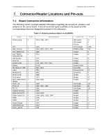
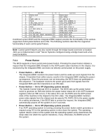
Intel®Server Board S1200BT TPS Connector/Header Locations and Pin-outs 7.4.2 Reset Button The platform supports a front control panel reset button. Pressing the reset button initiates a request forwarded by the Integrated BMC to the chipset. The BIOS does not affect the behavior of the reset button. 7.4.3 System Status Indicator LED The Intel® Server Board S1200BTL has a system status indicator LED on the front panel. This indicator LED has specific states and corresponding interpretation as shown in the following table. Table 27. System Status LED Indicator States Color Green Green State Solid on ~1 Hz blink Criticality Ok Degraded Amber ~1 Hz blink Non-critical Amber Solid on Critical, nonrecoverable Off N/A Not ready Description System booted and ready System degraded: Non-critical temperature threshold asserted. Non-critical voltage threshold asserted. Non-critical fan threshold asserted. Fan redundancy lost, sufficient system cooling maintained. This does not apply to non-redundant systems. Power supply predictive failure. Power supply redundancy lost. This does not apply to non-redundant systems. Correctable errors over a threshold of 10 and migrating to a spare DIMM (memory sparing). This indicates the user no longer has spared DIMMs indicating a redundancy lost condition. Corresponding DIMM LED should light up 4. Non-fatal alarm - system is likely to fail: CATERR asserted. Critical temperature threshold asserted. Critical voltage threshold asserted. Critical fan threshold asserted. VRD hot asserted. SMI Timeout asserted. Fatal alarm - system has failed or shutdown: Thermtrip asserted. Non-recoverable temperature threshold asserted. Non-recoverable voltage threshold asserted. Power fault/Power Control Failure. Fan redundancy lost, insufficient system cooling. This does not apply to non-redundant systems. AC power off, if no degraded, non-critical, critical, or non-recoverable conditions exist. Notes: 1. The BIOS detects these conditions and sends a Set Fault Indication command to the Integrated BMC to provide the contribution to the system status LED. 2. Support for upper non-critical limit is not provided in the default SDR configuration. However, if a user does enable this threshold in the SDR, then the system status LED should behave as described. There is no precedence or lock-out mechanism for the control sources. When a new request arrives, all previous requests are terminated. For example, if the chassis ID LED is blinking and the chassis ID button is pressed, then the chassis ID LED changes to solid on. If the button is pressed again with no intervening commands, the chassis ID LED turns off. Revision 1.0 95 Intel order number G13326-003
-
 1
1 -
2
-
3
-
4
-
5
-
6
-
7
-
8
-
9
-
10
-
11
-
12
-
13
-
14
-
15
-
16
-
17
-
18
-
19
-
20
-
21
-
22
-
23
-
24
-
25
-
26
-
27
-
28
-
29
-
30
-
31
-
32
-
33
-
34
-
35
-
36
-
37
-
38
-
39
-
40
-
41
-
42
-
43
-
44
-
45
-
46
-
47
-
48
-
49
-
50
-
51
-
52
-
53
-
54
-
55
-
56
-
57
-
58
-
59
-
60
-
61
-
62
-
63
-
64
-
65
-
66
-
67
-
68
-
69
-
70
-
71
-
72
-
73
-
74
-
75
-
76
-
77
-
78
-
79
-
80
-
81
-
82
-
83
-
84
-
85
-
86
-
87
-
88
-
89
-
90
-
91
-
92
-
93
-
94
-
95
-
96
-
97
-
98
-
99
-
100
-
101
-
 102
102 -
 103
103 -
 104
104 -
 105
105 -
 106
106 -
 107
107 -
 108
108 -
 109
109 -
 110
110 -
 111
111 -
 112
112 -
113
-
114
-
115
-
116
-
117
-
118
-
119
-
120
-
121
-
122
-
123
-
124
-
125
-
126
-
127
-
128
-
129
-
130
-
131
-
132
-
133
-
134
-
135
-
136
-
137
-
138
-
139
-
140
-
141
-
142
-
143
-
144
-
145
-
146
-
147
-
148
-
149
-
150
-
151
-
152
-
153
 |
 |
