Brother International MFC-7050C Service Manual
Brother International MFC-7050C Manual
 |
View all Brother International MFC-7050C manuals
Add to My Manuals
Save this manual to your list of manuals |
Brother International MFC-7050C manual content summary:
- Brother International MFC-7050C | Service Manual - Page 1
FACSIMILE EQUIPMENT SERVICE MANUAL MODEL: MFC7050C - Brother International MFC-7050C | Service Manual - Page 2
This publication is a Service Manual covering the specifications, construction, theory of operation, and maintenance of the Brother facsimile equipment. It includes information required for field troubleshooting and repair--disassembly, reassembly, and lubrication--so that service personnel will be - Brother International MFC-7050C | Service Manual - Page 3
CONTENTS 1. EQUIPMENT OUTLINE I-1 1.1 External Appearance and Weight I-1 1.2 Components I-1 2. SPECIFICATIONS I-2 - Brother International MFC-7050C | Service Manual - Page 4
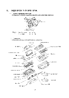
PCB Frame chassis Maintenance ASSY Lower cover Video PCB Interface PCB NCU PCB / Bottom plate 7%- , O.0 (75 I -1 Top cover Upper cover Document tray Paper tray Power supply PCB - Brother International MFC-7050C | Service Manual - Page 5
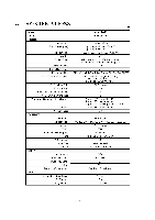
2. SPECIFICATIONS (1/3) Model MFC7050C Color White (1138) PRINTER Engine Type , Print Speed (ppm) Resolution (dpi) Thermal ink jet Up to 6 ppm/Mono, 300 x 600 Up to 3 ppm/Color 1200 x 1200, 600 x 600, 300 x 600 Emulation Printer Driver N/A Windows 3.1/3.11, Windows 95/98, NT Driver with - Brother International MFC-7050C | Service Manual - Page 6
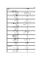
DUAL ACCESS Input/Output Width Help List Auto Reduction Message Center OGM ICM Recording Time Paging Toll Saver Fax & Voice Mail Box : Fax-on-demand MFC7050C Yes 6 256 (Error Diffusion) Yes (Send and Receive) N/A Yes N/A 12 X 2 100 Yes Yes Text (Light/Normal/Dark) Yes Yes Yes (name or tel number - Brother International MFC-7050C | Service Manual - Page 7
/Video Print PC-Fax Protocol Compliance Data Modem Bundled Software PC-FAX (Send/Receive) Internet Fax Color Viewer Color PC-FAX MFC7050C (3/3) N/A Yes Yes N/A N/A N/A N/A N/A N/A N/A N/A 2 MB N/A Yes (FAX/PRINTER, SCAN/PRINTER, COPY/PRINTER) Yes Bi Centro Yes (NTSC) CLASS 1 N/A Yes (SMSI) Yes - Brother International MFC-7050C | Service Manual - Page 8
CONTENTS 1. INSTALLING THE UPDATE DATA TO THE FACSIMILE EQUIPMENT II -1 - Brother International MFC-7050C | Service Manual - Page 9
75 or higher 8MB or greater (16MB recommended for Windows® 95) Windows@ 3.1/3.11 or Windows® 95/98 Connecting the facsimile equipment to your the lock wires. (4) Connect the other end of the interface cable to the printer port of your computer and secure it with the two screws. (5) Power on - Brother International MFC-7050C | Service Manual - Page 10
button, point to Programs, and then click MS-DOS Prompt to open an MSDOS window. (3) Type the drive letter where the update data and transfer utility are located. "Writing Flash" "Verifying Flash" Upon completion of the downloading, the equipment shows "Cycle Power Now." Disconnecting the facsimile - Brother International MFC-7050C | Service Manual - Page 11
-in, registration, feeding, and ejecting mechanisms 2.2.2 Ink jet printing and capping mechanisms 2.2.3 Carrier drive mechanism 2.3 Sensors and Actuators 3. CONTROL ELECTRONICS 3.1 Configuration 3.2 Main PCB 3.3 NCU PCB 3.4 Control Panel PCB 3.5 Power Supply PCB 3.6 Interface PCB III -1 III -2 III - Brother International MFC-7050C | Service Manual - Page 12
Fax Control Section Printer Control Section Print data V l/ . ( I V 1 1 r a Line NCU Speaker Scanner unit Ink jet printer unit Paper Power •. " - CIS unit - Ink-jet print heads feeding supply - Scanner motor (embedded in ink cartridges) mechanism •. i ... - Carrier transport - Brother International MFC-7050C | Service Manual - Page 13
mechanisms - Carrier drive mechanism ■ SENSORS AND ACTUATORS N Document feeding and ejecting mechanism 0 0 SCANNER MECHANISM Document O scanning mechanism Ink jet printing and head capping mechanisms Carrier drive mechanism Paper pulling-in, registration, feeding, and ejecting mechanisms - Brother International MFC-7050C | Service Manual - Page 14
2.1 Scanner Mechanism This mechanism consists of the top cover, automatic document feeder (ADF), document feed roller ASSY, document ejection roller ASSY, and document sensors. (For details about the sensors, refer to Section 2.3.) If the operator sets documents on the top cover and starts the - Brother International MFC-7050C | Service Manual - Page 15
2.1.1 Document feeding and ejecting mechanism To feed and eject documents, the scanner motor rotates counterclockwise. It rotates the sun gear 19/55 clockwise so that the planet gear 23 ASSY transmits the torque to the gear 19/47 and its gear train. After completion of paper ejection, the scanner - Brother International MFC-7050C | Service Manual - Page 16
, and ejecting mechanisms are driven by a single paper feed motor. ASF Paper Supply roller ASSY Carrier ASSY Main shaft Ink cartridge (Print head embedded in the bottom of the ink cartridge) Ink jet printing mechanism Sensor lever (Registration sensor actuator) Pinch rollers Paper pulling-in - Brother International MFC-7050C | Service Manual - Page 17
Secondary gear B If the paper feed motor rotates clockwise, the rotational torque is transmitted via the gear train to the supply gear built in the auto sheet feeder (ASF). The supply gear rotates once counterclockwise to pull in paper from the ASF, a sheet at a time. Since the gear is a sector - Brother International MFC-7050C | Service Manual - Page 18
also to the friction gear (2) which is engaged with the teeth of the supply gear, so the supply gear rotates and comes back to the initial position. Middle gear B (Idle gear) ASF / Supply gear Friction gear (2) Secondary gear C Friction gear (1), idling Secondary gear A (2) Feed gear Middle - Brother International MFC-7050C | Service Manual - Page 19
ASSY Sensor FPC Carrier home position sensor (Photointerrupter) Ink cartridges Main shaft Star wheel • Exit roller (Viewed from the left) (1) Ink jet printing This equipment uses drop-on-demand ink jet printing. The black cartridge and color cartridge install in the carrier, each of which has - Brother International MFC-7050C | Service Manual - Page 20
head wiper unit up. When the carrier travels to the left, the wipers clean ink remaining on the head surfaces and then the carrier's boss presses the wiper release lever Maintenance ASSY "a": Head cap unit guides "b": Wiper unit guides Cleaning with head wipers ff ( ss• Wiper release lever III - 9 - Brother International MFC-7050C | Service Manual - Page 21
transport motor controls horizontal motion. The motor rotation is transmitted via the motor pulley to the timing belt. The carrier, which is supported and guided by the main shaft, is secured to the timing belt. Clockwise and counterclockwise rotations of the carrier transport motor move the carrier - Brother International MFC-7050C | Service Manual - Page 22
the leading edge of a new page has reached the starting position and when the scan for that page is over. • Ink empty sensor which detects the density of a printed ink-empty mark. • Carrier home position sensor which detects whether the carrier is in the home position. Each of the above photosensors - Brother International MFC-7050C | Service Manual - Page 23
PCB Document sensor PCB of the control panel PCB ASSY Cover sensor actuator Cover sensor Cover sensor PCB Document rear sensor Document rear sensor actuator Ink empty sensor PCB Ink empty sensor Carrier home position sensor Sensor FPC Carrier Location of Sensors and Actuators III - 12 - Brother International MFC-7050C | Service Manual - Page 24
4-pin 4-pin 4-pin 7-pin 8-pin 10-pin 11-pin Sensor FPC Ink cartridges -FINK JET LPRINTER UNIT Carrier transport motor Paper feed motor Ink empty *6 sensor PCB LI LI LI Interface PCB 6-pin 36-pin Centronics interface Power supply PCB *1 On the main PCB 's the registration sensor. *2 On the - Brother International MFC-7050C | Service Manual - Page 25
Power 1, supply Interface Centronics interface driver L PCB driver I Scanner motor I Flexible I :flat cables Carrier transport motor driver Paper feed motor driver Speaker amplifiers Analog switch/ MODEM -011-0. operational amplifiers Carrier transport I motor I Paper feed motor I Ink - Brother International MFC-7050C | Service Manual - Page 26
pi1 P12 = = P10 F '2 = E.] P15 _ P18 1 l_ == = s- ll P17 r 1 Carrier transport motor driver El C7_ r7 1 El S.' = II P18 P5O Ll p4 L P8 Li Comparator Registration sensor Gate array Flash ROM Paper feed DRAM motor driver ROM Analog switch Operational amplifier MODEM III - 15 - Brother International MFC-7050C | Service Manual - Page 27
3.3 NCU PCB The NCU PCB switches the communications line to telephone or built-in MODEM, under the control of the main PCB. LINE EXTERNAL TELEPHONE HANDSET Surge absorber Dial pulse generator Line relay \ .(.O. ML relay) Loop current detector CTelephone circuit Line transformer MAIN PCB High - Brother International MFC-7050C | Service Manual - Page 28
3.4 Control Panel PCB The control panel PCB and the main PCB communicate with each other by serially transmitting commands and data. The control panel unit consists of a gate array, an LCD and LEDs, which are controlled by the gate array according to commands issued from the control CPU on the main - Brother International MFC-7050C | Service Manual - Page 29
5V) from a commercial AC power line. Both the +30V and +5V DC supplies are fed via the interface PCB to the main PCB. The +30V source is feeding documents and recording paper), carrier transport motor (for moving the carrier), thermal ink-jet print heads, and LED array of the CIS unit. The +5V source - Brother International MFC-7050C | Service Manual - Page 30
generates +22V and +11.75V supplies from the +30V source and +3.3V supply from the +5V source, and then feeds them to the main PCB. The +22V and +11.75V sources are stabilized and fed to the thermal ink-jet print heads embedded in the ink cartridges and the head driver IC on the main PCB - Brother International MFC-7050C | Service Manual - Page 31
to Access the Object Component ■ Disassembly Order Flow 1 .1 Ink Cartridges 1 .2 Interlock Keys 1 .3 Control Panel ASSY 1 .4 .16 Main PCB and Insulation Film 1 .17 Video PCB 1 .18 Ink Empty Sensor PCB ASSY 1 .19 Bottom Plate 1 .20 Power Supply PCB and Interface PCB 1 .21 NCU PCB 1 .22 Frame Chassis - Brother International MFC-7050C | Service Manual - Page 32
Roller ASSYs Sensor Lever (Registration sensor actuator) Earth Spring Exit Roller and Base Frame Large Feed Roller ASSY Gear Plate ASSY Ink Foam Harness Routing 2. LUBRICATION [ 1 ] Document feed roller ASSY and document ejection roller ASSY [ 2 ] Control panel locks [ 3 ] Scanner frame ASSY and - Brother International MFC-7050C | Service Manual - Page 33
problems by mishandling, observe the following precautions during maintenance work. (1) Unplug the power cord from the power outlet before replacing parts or units. When having access to the power supply has no carrier locking mechanism. Put the removed ink cartridges in a vinyl bag and seal it up in - Brother International MFC-7050C | Service Manual - Page 34
(Min. 2) Bottom plate Taptite, cup S M3x6 Taptite, bind B M4x12 2 78 ±20 (8 ±2) 20 to 59 (2 to 6) 6 98 ±20 (10 ±2) Min. 29 (Min. 3) Power supply PCB Taptite, cup S M3x6 2 49 ±20 (5 ±2) Min. 20 (Min. 2) Grounding wire for AC cord Screw, pan (washer) M4x6DB 1 49 ±20 (5 ±2) Min. 20 (Min - Brother International MFC-7050C | Service Manual - Page 35
an external telephone set if connected. (Not shown below.) (2) Remove - the document wire extension - the document tray, - the paper tray, and - the ink cartridges if loaded. (Not shown below.) PC interface cable Telephone line cord Document wire extension Handset and curled cord N Document tray - Brother International MFC-7050C | Service Manual - Page 36
• Disassembly Order Flow Ink cartridges Control panel ASSY Interlock keys Panel rear cover - ADF parts sensor PCB Upper cover C) Main PCB Insulation film Video PCB 18 Ink empty sensor PCB ASSY Sensor cover Ink empty sensor PCB Sensor holder Star wheels and springs Frame chassis ASSY - Brother International MFC-7050C | Service Manual - Page 37
disassembly jobs, both of the ink cartridges should be removed. The following procedure should apply only when you need to make operation checks. If you have initialized the EEPROM, plugging the power cord into an electrical socket will show the "SET CARTRIDGES" and "PLS OPEN COVER" alternately - Brother International MFC-7050C | Service Manual - Page 38
into the slot and press it to the rear until it snaps into place. V of Color ink cartridge Black ink cartridge (3) After loading ink cartridges, close the top cover. The "DID YOU CHANGE?" and "RIGHT:1.YES 2.NO" messages appear alternately. (4) Press the 1 key. The "DID YOU INSTALL?" and "1.BLACK - Brother International MFC-7050C | Service Manual - Page 39
1.2 Interlock Keys (1) Remove the interlock keys from the carrier. Interlock key (gray) Interlock key (violet) Carrier Hole Interlock key ■ Reassembling Notes • Set the violet interlock key at the left and the gray one at the right. • As shown above, fit the boss of each interlock key in the - Brother International MFC-7050C | Service Manual - Page 40
1.3 Control Panel ASSY (1) Slightly open the control panel ASSY. (2) Push the right and left arms of the control panel ASSY outwards (in the direction of arrow 0) with your thumbs and open the control panel ASSY further (arrow 0) to unhook those arms from bosses "x" provided on the scanner frame - Brother International MFC-7050C | Service Manual - Page 41
antivibration rubber with this line. Shield film Antistatic brush 1 Panel rear cover Antistatic brush 2 (4) To remove the document pressure bar, pull either of supports "a" provided on the panel rear cover outwards and then lift the pressure bar up and towards the rear to release the three tabs - Brother International MFC-7050C | Service Manual - Page 42
(6) Remove the two screws from the panel rear cover. (7) Unhook the panel rear cover from eight "X" latches provided on the control panel and lift up the panel rear cover. (8) Fully turn the document front sensor actuator to the rear and lift it up. (9) Unhook the document sensor PCB from two "Y" - Brother International MFC-7050C | Service Manual - Page 43
screwdriver ■ Reassembling Notes • Before reinstalling the LCD to the control panel, wipe fingerprints or dust off the LCD surface and control panel window with a soft cloth. • A new LCD is covered with a protection sheet. Before installing it, remove the protection sheet. • To put the LCD back - Brother International MFC-7050C | Service Manual - Page 44
1.5 Document Feed Roller ASSY and Document Ejection Roller ASSY (1) Lightly push down arm rib "a" and shift the document feed roller ASSY to the right and upwards. (2) Lightly push down arm rib "b" and shift the document ejection roller ASSY to the right and upwards, without removing the shield film - Brother International MFC-7050C | Service Manual - Page 45
1.6 Scanner Frame ASSY (1) You can remove the following parts from the top of the scanner frame ASSY without taking out the ASSY from the top cover. • CIS film • Shield film • CIS unit (shown on the next page). Lightly pull up the arm, move the CIS unit to the left, and lift up the right edge of the - Brother International MFC-7050C | Service Manual - Page 46
CIS unit CIS harness CIS leaf springs CIS leaf spring ti Scanner frame ASSY Arm CIS unit (2) Remove the two screws from the scanner frame ASSY. (See the illustration on the next page.) IV - 14 - Brother International MFC-7050C | Service Manual - Page 47
(3) Lift up the rear edge of the scanner frame ASSY to release the three pawls provided on the front end from the top cover, then hold up the ASSY and disconnect the scanner motor harness and CIS harness (if the CIS is mounted). (4) Take off the grounding terminals by removing the screws. Scanner - Brother International MFC-7050C | Service Manual - Page 48
(5) Turn the scanner frame ASSY upside down. (6) Remove the screw from the scanner motor and turn the motor clockwise to release from the latch. v. Scanner frame ASSY placed upside down (Rear) Latch 0 0 Scanner motor Screw, pan (washer) M3x6DA (7) Remove the pinch roller leaf spring by removing - Brother International MFC-7050C | Service Manual - Page 49
(9) Remove the pressure roller leaf springs by pulling them in the direction of arrows T and 0 in this order as shown below. Then remove the pressure rollers and shaft. Pressure roller shaft r / Pressure rollers Pressure roller leaf springs Scanner frame ASSY placed upside down (Front) 0 0 000 - Brother International MFC-7050C | Service Manual - Page 50
(11) Take off the scanner drive unit by removing the two screws. The separation roller gear also comes off. (Front) Scanner frame ASSY placed upside down C Taptite, cup B M3x10 Scanner drive unit Taptite, cup B M3x8 Separation roller gear (12) Push down the CIS side spring to release it from the - Brother International MFC-7050C | Service Manual - Page 51
■ Reassembling Notes • When reinstalling the scanner motor, fit it in the latch provided on the scanner frame with the connector facing up and then secure it with the screw. (See page IV-16.) • When setting the scanner frame ASSY back into place, - secure the grounding terminals to the scanner frame - Brother International MFC-7050C | Service Manual - Page 52
1.7 Rear Cover (1) Remove the four screws from the rear cover. (2) Slightly pull the top of the rear cover to the rear and lift up the rear cover. Rear cover Taptite, bind B M4x12 Top cover I® Rear cover Tabs Lower cover IV - 20 - Brother International MFC-7050C | Service Manual - Page 53
1.8 Auto Sheet Feeder (ASF) (1) Remove two screws "a" that secure the ASF to the frame chassis. (2) Remove screw "b" that secures the ASF to the paper feed motor bracket. (3) At the left end of the ASF (when viewed from the rear), press the latch inwards to unhook it from the square hole provided - Brother International MFC-7050C | Service Manual - Page 54
1.9 Inner Cover (1) Remove the three screws from the inner cover. (2) Remove the inner cover. To release the bottom end of the inner cover from the guide provided on the upper cover, lightly pull the top of the inner cover to the rear until it comes out of the upper cover and - Brother International MFC-7050C | Service Manual - Page 55
1.10 Battery ASSY Disconnecting the battery harness with the power cord unplugged will lose the settings (e.g., calendar clock, voice messages, and received FAX data) stored in the RAM. After connecting the battery harness, therefore, you may need to make those settings. To remove the upper cover - Brother International MFC-7050C | Service Manual - Page 56
1.11 Upper Cover ASSY (1) Disconnect the following six harnesses (seven harnesses if the battery ASSY has not been removed) from the main PCB: • Cover sensor harness • Panel-main harness • CIS harness • Speaker harness • Hook switch harness • Scanner motor harness • (Battery harness if not - Brother International MFC-7050C | Service Manual - Page 57
Ink empty sensor harness Cover sensor harness Panel-main (Top) harness (Not used.) ( harness CIS harness Carrier flat cables P18 PS Carrier transport motor harness 8 0 Power supply 1 harness Power supply 2 harness Speaker harness 66 P4I-. U = 2 NCU harness Battery harness Hook switch - Brother International MFC-7050C | Service Manual - Page 58
page.) The grounding wires, panel-main harness, and CIS harness also come off. (6) Cut off the binder that secures the scanner motor harness to the support provided on the top cover. IV - 26 - Brother International MFC-7050C | Service Manual - Page 59
Scanner motor harness Support Binder Routing the scanner motor harness Slot and grounding wires Hinge R 50 ± 5 mm Ferrite cores • As illustrated above, route the scanner motor harness and secure it to the support with a binder so that the distance from the ferrite core to the secured point comes to 50 ±5 - Brother International MFC-7050C | Service Manual - Page 60
• When securing the hinge L, route the panel-main harness and CIS harness as illustrated on the previous page, taking care not to pinch them between the hinge and top cover. • When securing the hinge R, route the two grounding wires as illustrated on the previous page. • If the stopper shaft has - Brother International MFC-7050C | Service Manual - Page 61
1.13 Handset Mount and Hook Switch PCB ASSY (1) Open the top cover. (2) Remove the two screws from the handset mount. (3) Twist the handset mount so that it tilts over to the left and its upper end works out of the bosses provided on the upper cover. NOTE: Do not pull the handset mount away from the - Brother International MFC-7050C | Service Manual - Page 62
(4) Disassemble the handset mount by unhooking two latches "a" of the upper handset mount with a flat screwdriver. (5) Remove the hook switch PCB ASSY by unhooking latch "b." (6) Disconnect the hook switch harness from the hook switch PCB. Upper handset mount Lower handset mount ,?, .41 70' Latch - Brother International MFC-7050C | Service Manual - Page 63
upper cover upside down. (2) Take out speaker harness from the three guides and pull up the speaker. (3) Remove the screw and lift up the speaker spring. (4) Take out the cover sensor harness from the three guides and unhook the cover sensor PCB. Taptite, bind B M4x12 Speaker spring - Brother International MFC-7050C | Service Manual - Page 64
transport motor harness Carrier flat cables Centro 1 harness Centro 2 harness Main PCB ri Power supply 1 harness (Rear) Power supply 2 harness Paper feed motor harness Video capture harness NCU harness Ink empty sensor harness Cover sensor harness Panel-main (Top) harness (Not used.) (Not - Brother International MFC-7050C | Service Manual - Page 65
(3) Remove the four screws from the main PCB, then take off the main PCB while tilting the sensor lever (registration sensor actuator) to the rear. (4) Remove the insulation film from tabs provided on the frame chassis in the direction of arrows O and O. Main PCB Registration sensor Sensor lever ( - Brother International MFC-7050C | Service Manual - Page 66
Setting up the main PCB after replacement Important NOTE: When replacing the main PCB, it is recommended that you replace all ink cartridges in order to maintain accurate ink level information. Replaced with a new main PCB? N (Replaced with one used) Flash ROM or masked ROM on the new main PCB? - Brother International MFC-7050C | Service Manual - Page 67
video capture harness from the video PCB. (2) Remove the screw and take out the video PCB. (3) Take out the video capture harness from the three guides. Disconnect it from the main PCB, if connected, then pull it out to the rear. Video capture harness Taptite, cup B M3x10 Video PCB Frame chassis - Brother International MFC-7050C | Service Manual - Page 68
frame chassis at each of the rear and right side. (2) Take out the ink empty sensor harness from the guide slot and the latches. (3) Unhook the ink empty sensor PCB ASSY from the base frame in the direction of arrows 0, 0, and O. Ink empty sensor harness Do not loosen or remove these screws. (Rear - Brother International MFC-7050C | Service Manual - Page 69
PCB Star wheel Star wheel spring Sensor holder Setting the star wheel and spring Star wheel spring Star wheel ■ Reassembling Notes • When setting the ink empty sensor PCB to the sensor holder, face the device-mounting side down. • When setting the sensor cover to the sensor holder, fit hole - Brother International MFC-7050C | Service Manual - Page 70
Remove two "x" screws and six "y" screws. (2) Lightly lift up the rear edge of the bottom plate and disconnect the centro harnesses (1 and 2) and power supply harnesses (1 and 2). (3) If the upper cover ASSY has not been removed so that the grounding wire has not been released from the frame chassis - Brother International MFC-7050C | Service Manual - Page 71
from the interface PCB. (5) Remove two screws "f" and take off the interface PCB. Interface PCB Power supply PCB AC cord ?„ z„ Grounding wire (which might be connected to the frame chassis) Bottom plate "d": Taptite, cup S M3x6 "e": Screw, pan (washer) M4x6DB "f": Screw, pan M3x6 "z": - Brother International MFC-7050C | Service Manual - Page 72
1.21 NCU PCB (1) Remove the screw from the NCU PCB. (2) Lightly lift up the NCU PCB and disconnect the NCU harness. Taptite, bind B M4x12 NCU PCB NCU harness (Rear) Lower cover placed upside down IV - 40 - Brother International MFC-7050C | Service Manual - Page 73
ASSY Video grounding plate NCU harness (The harness end equipped with a ferrite core should be at this side.) Centro harnesses Power supply harnesses (Their harness ends equipped a ferrite core should be at this side.) 40- Lower cover I® (Front) "a": Taptite, bind B M3x10 "b": Taptite, bind - Brother International MFC-7050C | Service Manual - Page 74
1.23 Paper Feed Motor (1) On the front side of the frame chassis, loosen screw "g" in order to allow a screwdriver to access screw "h." (2) Remove two screws "h" and take out the paper feed motor. Frame chassis Viewed from the front "g" and "h": Taptite, bind S M3x5 Loosen this screw to allow a - Brother International MFC-7050C | Service Manual - Page 75
1.24 Carrier Transport Motor, Main Shaft, Timing Belt, and Carrier ASSY (1) Move the carrier to the center of its travel (in the direction of arrow (D). (2) Remove the spring cuff. (3) While pressing the idle pulley holder to the right (in the direction of arrow 0), remove the timing belt from the - Brother International MFC-7050C | Service Manual - Page 76
ASF's latch will be fitted in this opening.) Carrier transport motor harness (Ink empty sensor harness) (Right) Hole provided in the frame chassis Taptite, At the left end, remove the main shaft holder. (7) While supporting the left end of the main shaft, take up the right end and pull out - Brother International MFC-7050C | Service Manual - Page 77
Carrier's support Top edge of the frame chassis ( Carrier Main shaft holder B Right end of the shaft Main shaft holder Main shaft holder B Main shaft holder Frame - Brother International MFC-7050C | Service Manual - Page 78
■ Reassembling Notes • If you replace the carrier transport motor with a new one, attach a ferrite core to the harness of the new motor so that the ferrite core comes to 30 ±10 mm away from the harness end at the connector housing side. Wind the harness around the ferrite core by two turns and then - Brother International MFC-7050C | Service Manual - Page 79
1.25 Idle Pulley Holder (1) Move the carrier to the center of its travel. (2) Remove the spring cuff if not removed yet. (3) If the timing belt is installed, remove the timing belt from the carrier transport motor gear and the idle pulley while pressing the idle pulley holder to the right. (4) - Brother International MFC-7050C | Service Manual - Page 80
1.26 Maintenance ASSY (1) On the rear side of the frame chassis, unhook the two latches of the maintenance ASSY. NOTE: The maintenance ASSY is glued to the frame chassis at four points, so you need to remove the glue. Frame chassis Cutout 0 Gripper ring Cutout Boss Latches Boss Maintenance ASSY - Brother International MFC-7050C | Service Manual - Page 81
1.27 Pinch Roller ASSYs (1) Unhook the four feed springs from the rear of the frame chassis. (2) Pull out the four pinch roller ASSYs and springs to the rear. Frame chassis (Rear) Feed springs Pinch rollerASSYs ■ Reassembling Notes • If you have removed the sensor lever (registration sensor - Brother International MFC-7050C | Service Manual - Page 82
1.28 Sensor Lever (Registration sensor actuator) (1) Unhook the sensor lever (registration sensor actuator) in the direction of arrow CI and remove it in the direction of arrows 0 and O. (2) Remove the sensor lever spring. g Hook k&.. - Brother International MFC-7050C | Service Manual - Page 83
1.29 Earth Spring (1) Unhook the looped end of the earth spring from the base frame ("a") and remove the spring from the frame chassis ("b"). p Frame chassis 0 Gss7 Feed roller shaft Earth spring (Front) Earth spring Exit roller Base frame Large feed rollerASSY Viewed from the bottom • - Brother International MFC-7050C | Service Manual - Page 84
1.30 Exit Roller and Base Frame (1) From each of the right and left ends of the exit roller shaft, remove the E-ring. (2) At the left end of the exit roller, pull the arm of the bearing outwards and turn it clockwise (when viewed from the left), then pull it out to the left. (3) Pull the left end of - Brother International MFC-7050C | Service Manual - Page 85
(4) Remove the two screws from the bottom of the base frame. (5) Push up the rear end of the base frame to unhook it and then pull out the base frame to the front. Frame chassis 0 0 b 0 O00 o, Cutout Hook A Taptite, bind P M3x8 05 0 0 - 6v1e, ° .`" Cutout Hook Boss Boss Base frame - Brother International MFC-7050C | Service Manual - Page 86
1.31 Large Feed Roller ASSY (1) At each of the right and left ends of the large feed roller shaft, pull the arm of the bearing outwards, turn it clockwise (when viewed from the left), and pull it out. NOTE: These bearings may be glued to the frame chassis and gear plate, so you need to remove the - Brother International MFC-7050C | Service Manual - Page 87
1.32 Gear Plate ASSY (1) Remove the two screws. (2) Slightly pull the gear plate ASSY to the right to unhook it from the tab of the frame chassis, and then remove it to the rear. Gear plate ASSY Square hole 0 0 Frame chassis -0 c J1 Tab (Front) Taptite, bind S M3x5 Friction gear Secondary - Brother International MFC-7050C | Service Manual - Page 88
1.33 Ink Foam (1) Take up the ink foam from the lower cover. Ink foam ....7... 0,555,79'' k. 11 I® Er Lower cover IV - 56 - Brother International MFC-7050C | Service Manual - Page 89
(Adhesive tape) CIS harness Battery harness 0 Speaker harness 0 Ink empty sensor harness Carrier transport motor harness (Adhesive tape) Do this opening. Carrier flat cables Power supply 1 harness Power supply 2 harness Power supply 1 harness Power supply 2 harness Hook switch harness Video - Brother International MFC-7050C | Service Manual - Page 90
2. LUBRICATION Apply the specified lubricants to the lubrication points as shown below. Lubricant type (Manufacturer) Molykote EM-30LG or EM-30L (Dow Corning) Molykote EM-D110 (Dow Corning) NYE NYOGEL 744 (William F. Nye Company) Thin coat of grease (1 mm3) Lubricant amount Half of a rice-sized - Brother International MFC-7050C | Service Manual - Page 91
panel lock (leaf spring) Scanner frame ASSY EM1 e [ 3 ] Scanner frame ASSY and separation roller gear Separation roller Separation roller gear Separation roller support EM1 EM1 EM1 O A A-A @HI O EMO 5 Scanner frame ASSY A placed upside down IV - 59 Scanner frame ASSY placed upside down - Brother International MFC-7050C | Service Manual - Page 92
[ 4 ] Top cover lock spring /\ Upper cover (EMO 5) EMO 5 CEM0.5) .1/ (EM0.5) Top cover lock spring Apply a thin coat of grease with a brush. [ 5 ] Gear plate ASSY Motor bracket Friction gear NY1 NY1 O Friction gear (9) OO O O O NY1 Secondary gear B NY1 NY1 Paper feed motor gear IV - 60 - Brother International MFC-7050C | Service Manual - Page 93
[ 6 ] Hinges Hinge L Hinge R EMD1) Bend the hinge EMD1) and apply grease. EMD1) EMD1) [ 7 ] Frame chassis ASSY Apply grease to the front and rear sides with a brush. NY2 LJ Frame chassis 0 0 0 Main shaft IV - 61 NY2 Apply grease with a brush. - Brother International MFC-7050C | Service Manual - Page 94
[ 8 ] Idle pulley holder 0 Apply grease to the rear side. NY1 Idle pulley Idle pulley holder NY1 [ 9 ] Maintenance ASSY I 0 0 0 0 1./V1,1111,,NNV 0 NY1 0 00 NY1 NY1 NY1 Maintenance ASSY IV - 62 - Brother International MFC-7050C | Service Manual - Page 95
[ 10 ] Exit roller ASSY Frame chassis Base frame N NY0 5) Exit roller ASSY [ 11 ] Large feed roller ASSY Frame chassis 0 Oo Op NY0.5) Large feed roller ASSY CNY0.5) IV - 63 - Brother International MFC-7050C | Service Manual - Page 96
-MODE FUNCTIONS 3.1 EEPROM Parameter Initialization 3.2 Printout of Scanning Compensation Data 3.3 Firmware Switch Setting 3.4 Operational Check of Control Panel PCB 3.5 Sensor Operational Check 3.6 EEPROM Customizing 3.7 Ink Dot Counter Initialization V-1 V-2 V-4 V-4 V-5 V-7 V-18 V-19 V-20 V-20 - Brother International MFC-7050C | Service Manual - Page 97
1. ENTRY INTO THE MAINTENANCE MODE To make the facsimile equipment enter the maintenance mode, press the Function, *, 2, 8, 6, and 4 keys in this order. IC- Within 2 seconds-1 The equipment beeps for approx. one second and displays "11 MAINTENANCE III " on the LCD, indicating that it is placed in - Brother International MFC-7050C | Service Manual - Page 98
Panel PCB (Check of Keys and Buttons) 3.3 (V-7) 3.4 (V-18) 32 Sensor Operational Check 3.5 (V-19) 74 EEPROM Customizing 3.6 (V-20) 81 Ink Dot Counter Initialization 3.7 (V-20) 91 EEPROM Parameter Initialization (except the telephone number 3.1 (V-4) storage area) 99 Exit from the - Brother International MFC-7050C | Service Manual - Page 99
them to access user-accessible selectors which are shaded in the firmware switch tables in Subsection 3.3. The service personnel should instruct end users to follow the procedure OnIOR Color Printer Reset Priority Ink Management Englaer Reduce Copy Sort (Photo Stop Start 0 key Stop key V- 3 - Brother International MFC-7050C | Service Manual - Page 100
of the EEPROM areas, but entering 91 does not initialize some areas, as listed below. Data item Function code Maintenance-mode functions User switches Firmware switches Remote activation code Telephone function registration Station ID data One-touch dialing Speed dialing Group dialing 01 All of - Brother International MFC-7050C | Service Manual - Page 101
3.2 Printout of Scanning Compensation Data ■ Function The equipment prints out the white and black level data for scanning compensation. ■ Operating Procedure Do not start this function merely after powering on the equipment but start it after carrying out a sequence of scanning operation. Unless - Brother International MFC-7050C | Service Manual - Page 102
WHITE LEVEL DATA x0C B3 B2 81 DE E8 E9 ER EA EC ED ED ED ED EE EE EE EF EF EF EF ED EE EF FO FO Fl FO F3 F3 F3 F3 F3 F5 F4 F5 F4 F3 F4 F3 F3 F3 F3 F3 F2 F5 F6 F6 F7 F7 F6 F6 F6 F6 F7 F6 F6 F6 F7 Fe F7 F8 F8 F8 F9 F7 F8 F8 F8 F9 F9 F9 F9 FO FA F9 F9 F9 F9 F9 FA F9 FA FA FA FB FA FC FB FA FB F9 FA FA - Brother International MFC-7050C | Service Manual - Page 103
3.3 Firmware Switch Setting ■ Function The facsimile equipment incorporates the following firmware switch functions (WSW01 through WSW36) which may be activated with the procedures using the control panel keys and buttons. The firmware switches have been set at the factory in conformity to the - Brother International MFC-7050C | Service Manual - Page 104
-digit number is entered for double-digit firmware switch numbers, the equipment will automatically return to the initial stage of the maintenance mode. ■ Note The user-accessible selectors of the firmware switches are shaded in the tables given on the following pages. V - 8 - Brother International MFC-7050C | Service Manual - Page 105
and busy tone detection) Selector No. 1 I 4 Function Not used. 5 Busy tone detection in automatic sending mode 6 7 8 Not used. Setting and Specifications • No. 5 6 00 : 01 : 10 : 11 : No detection Detection only after dialing No detection Detection before and after dialing • Selectors 5 and - Brother International MFC-7050C | Service Manual - Page 106
length of calling signal (Ci) Max. OFF time length of calling signal (Ci) Detecting time setting Not used. Setting and Specifications No. 1 2 0 0 0 1 1 0 1 1 No. 3 4 0 0 0 1 1 0 1 1 No. 5 6 0 0 0 1 1 0 1 1 : 300 ms (in the U.S.A. and Canadian versions) : 500 ms : 700 ms : 900 ms : 6 sec. : 7 sec - Brother International MFC-7050C | Service Manual - Page 107
3 4 5 8 WSW13 (Modem setting) Function Cable equalizer Reception level Modem attenuator Setting and Specifications No. 1 2 00 : 01 : 10 : 11 : No. 3 4 00 : dB 1: 1 dB The modem should be adjusted according to the user's line conditions. • Selectors 1 and 2: Cable equalizer These selectors - Brother International MFC-7050C | Service Manual - Page 108
setting) Selector No. Function 1 Frequency band selection 2 (Lower limit) 3 Frequency band selection 4 (Upper limit) 5 I Not used. 8 Setting and Specifications No. 1 2 0 0 : 0 1 : 1 0 : 1 1 : No. 3 4 0 0 : 0 1 : 1 X : 13 Hz 15 Hz 23 Hz 20 Hz 30 Hz 55 Hz 70 Hz • Selectors 1 through - Brother International MFC-7050C | Service Manual - Page 109
These selectors should be used if the facsimile equipment malfunctions in overseas communications. According to the communications error state, select the signal specifications. Setting selector 2 to "1" allows the equipment to use 1100 Hz CED signal instead of 2100 Hz in receiving operation. This - Brother International MFC-7050C | Service Manual - Page 110
Selector No. 1 I 5 6 8 WSW21 (TAD setting) Function Max. waiting time for voice signal Setting and Specifications No. 1 2 3 4 5 0 0 0 0 0 0 0 0 0 1 0 0 0 1 0 0 0 0 1 1 I 0 1 0 0 0 I 11111 : No detection : 1 sec. : 2 sec. : 3 sec. I : 8 sec. I : 31sec. Not used. NOTE: Selectors 1 through 8 are - Brother International MFC-7050C | Service Manual - Page 111
external telephone in the external TAD mode or via the facsimile equipment in F/T mode) Not used. Setting and Specifications No. 6 7 0 0 : 0.5 (A) 01 : 1 (B) 1 0 : 1.5 (C) 11 : 2 (D) NOTE: Selectors 6 and 7 are applicable to those models equipped with a built-in TAD. • Selectors 6 and - Brother International MFC-7050C | Service Manual - Page 112
No. 1 I 3 4 I 8 WSW30 (Function setting 2) Function Detection level of dial tone or busy tone for the built-in TAD operation Setting and Specifications No. 1 2 3 000 : 001 : 010 : 011 : 100 : 101 : 110 : 111 : -38.0 dBm (A) -39.5 dBm (B) -41.0 dBm (C) -42.5 dBm (D) -44.0 dBm (E) -45.5 dBm - Brother International MFC-7050C | Service Manual - Page 113
these selectors, it will disconnect the line. WSW36 (Function setting 4) Selector No. 1 2 8 Function ECP mode* Not used. Setting and Specifications 0: ON 1: OFF *ECP (Enhanced Capabilities Port) • Selector 1: ECP mode The ECP mode enhances the normal bidirectional communications between the - Brother International MFC-7050C | Service Manual - Page 114
The equipment returns to the initial stage of the maintenance mode. brother 7O5OC Function Se,t qp CHco)ok - alume 1 BC.?") Center Voice 0 0 Fax Record Erase Play (03 (03 (O) Color Printer On/Off Line Reset Priority Ink Management (O) (g) (O) (O) Enlarge Reduce (g) (g) Sort Photo C48) C- - Brother International MFC-7050C | Service Manual - Page 115
13 sensors operate correctly. - Document front sensor - Document rear sensor - Cover sensor Registration sensor Hook switch Carrier home position sensor - Ink empty sensor ■ Operating Procedure (1) Press the 3 and 2 keys in this order in the initial stage of the maintenance mode. The equipment - Brother International MFC-7050C | Service Manual - Page 116
and returns to the initial stage of the maintenance mode. 3.7 Ink Dot Counter Initialization ■ Function This function resets the ink dot counters (for black and color ink) to zero and sets the count-up value designed for starter ink cartridges. Accordingly, when the power is first applied after this - Brother International MFC-7050C | Service Manual - Page 117
2.1 Introduction 2.2 Precautions 2.3 Checking prior to Troubleshooting 2.4 Troubleshooting Procedures [ 1 ] Control panel related [ 2 ] Telephone related [ 3 ] Communications related [ 4 ] Paper/document feeding related [ 5 ] Print-image related [ 6 ] PC-driven or video capture-driven - Brother International MFC-7050C | Service Manual - Page 118
ERROR INDICATION To help the user or the service personnel promptly locate the cause of a problem (if any), the facsimile , see below. Error messages on the LCD Messages on the LCD CHECK PAPER PRINTER JAM COVER OPEN DOCUMENT JAM Probable Cause The registration sensor detects no recording paper - Brother International MFC-7050C | Service Manual - Page 119
is possible.) This message appears when the power is first applied to the equipment after initialization of the ink dot counter in the EEPROM on the main PCB, prompting the user to set ink cartridges. If this message appears, open and close the top cover. The message may disappear if opening/closing - Brother International MFC-7050C | Service Manual - Page 120
the troubleshooting procedures, so this section covers some sample problems. However, those samples will help service personnel pinpoint and repair other defective elements if he/she analyzes and examines them well. 2.2 Precautions Be sure to observe the following to prevent the secondary troubles - Brother International MFC-7050C | Service Manual - Page 121
Recording paper Check that: (1) A recommended type of recording paper is used. (2) The recording paper is not dampened. Ink cartridges (1) Check that both of two ink cartridges are loaded. VI - 4 - Brother International MFC-7050C | Service Manual - Page 122
2.4 Troubleshooting Procedures [ 1 ] Control panel related Trouble (1) LCD shows nothing. (2) Control panel inoperative. Check: • Panel-main harness • Control panel PCB • Power supply PCB • Main PCB • Interface PCB • Power supply harnesses (1 and 2), connecting the interface PCB and main PCB with - Brother International MFC-7050C | Service Manual - Page 123
(1) No tone is transmitted. • Main PCB • NCU PCB • NCU harness Check: [ 4 ] Paper/document feeding related Trouble (1) Neither "COPY: PRESS COPY" nor "FAX: NO. & START" message appears although documents are set. (2) Document not fed. (3) Document double feeding (4) Document jam (5) Recording - Brother International MFC-7050C | Service Manual - Page 124
is abnormal, proceed to the following checks: Trouble (1) Completely blank Action to be taken At the scanner Check the following components: - CIS harness - Main PCB - CIS unit (2) Random color (3) All black At the printer • Check each of the ink cartridges to confirm that the transparent tape - Brother International MFC-7050C | Service Manual - Page 125
remove dust or air bubbles from its nozzles. (If the problem persists, replace the ink cartridge(s).) • Replace the main PCB, the interface PCB, and power supply PCB. At the scanner Check the following components: - CIS unit At the printer • Check whether paper is in abnormal contact with any other - Brother International MFC-7050C | Service Manual - Page 126
viscosity has been increased, so replace it. • Replace the ink cartridge(s). • Replace the main PCB. • Replace the power supply PCB. • Replace the interface PCB. (9) Random missing dots - - At the printer • For each of the two ink-jet print heads, perform the head cleaning operation several times - Brother International MFC-7050C | Service Manual - Page 127
rollers. (11) Stained leading edge of recording paper At the printer • Clean the nozzle ends of the ink-jet print heads embedded in the ink cartridges. [ 6 ] PC-driven or video capture-driven printing Trouble Check: (1) PC-driven printing is impossible. (2) Video capture-driven printing - Brother International MFC-7050C | Service Manual - Page 128
the above procedure, the equipment stops the procedure and returns to the initial stage of the maintenance mode. • EEPROM Customizing Codes List Versions U.S.A. CANADA Model MFC7050C 1001 0002 - Brother International MFC-7050C | Service Manual - Page 129
I 2 3 V 4 5 6 +3.3V +3.3V +3.3V +3.3V +3. 3V 01 3 NG 857 040 104 R112 22K N 17 AMFPG IR1 3 22K 105 CLAMP I N GPI 00 208 SPOND44A c• NG -I- 019 NG SOV SOT 103BC GS°N 1 ss Gi BATRSTN 66 B C WNPROT N 3 .0 N VBAT BAT RST N 5 PWRDWNN S WRP ROT N gc , '7. ,..4 ACI ACI ,, ...... - Brother International MFC-7050C | Service Manual - Page 130
2 3 V 4 5 6 120 +se SOV 0149 °_, ° 00 1 04- 01 50 G 6 3 _.__,..---II--.Golo4 Gel o4 .-II-. 21 6 3722 42 V00 V00 G G G VO0 R. 14 RASOB GisA DBUS PDO Di 02 03 04 Ds O6 07 Da D' 010 011 Di 2 Di 3 01 4 01 5 13 RMWEB c 1 6,,, WE 29 RMOEB O11A 2 K14 : DE. gg UOASB G. , DA 000 3 - Brother International MFC-7050C | Service Manual - Page 131
I 2 3 V 4 5 6 +3.3V +3. 3V .5, M5V +3. 3V O OOO G2rI 6.±C 34Ov R258 11OK O2O2 GO1O4 SO VO-I o--I OSOV .O6 ' , o O2O5 GO1O4 A 6O1O4 OO HI - OSO V r,1 G232 GO33O R259 .3O O229 OO1O4 8 9 1OOK GO1O4 - dl ''' G458 A R213 , o (o w c.4 o .- co R221 + D NO - Brother International MFC-7050C | Service Manual - Page 132
1 2 3 V 4 PN2GU1 +Bv +30V 0 10 12 1TG0G215072 SOU .G.2..5, 2 ., 0O2T5G114 HA I I2 I 1 j L20 011 GMLL SOV _rle , e, R562A05,1 +3. 3V 30R0ET +5V 0O2T7A114YK r I ____, DTG11 4Y HA I I PLS 4A tkisV 6 171a20040 .. 002221704 S WIV +30V 4 NN3J M2058 1 (0G22G41142054) MOV M5V j - Brother International MFC-7050C | Service Manual - Page 133
1 2 3 V 4 5 P18 PS1 2 S0V 3 4 5 6 +22 VONT 7 B7 B- PH ( BLACK) 55G • 51., +O14 10O1100// S0V +3. 3V +G13 10V/100P S0V _ O140 , OO1 04 PS2 711 .75V 012 GZ B15 S0V 5 +30V 6 +22V RS c-. 3. OK 1 / 4W S0V B 30RET e.s, P H P10 R MOT 1 4 5 2 -/ 527 M T 02 002 F 2 OUT1 I - Brother International MFC-7050C | Service Manual - Page 134
1 2 3 4 5 6 P15 GEN 1 7 fil 0 a 1: u 9 - ID 8 u 0 • B106 PH RA15 1Y, za ry o c, I L.A A, . RA11 3.3K x4 RA13 3.3K x4 i v. o II 02 I I, c4 ..- i v o 11 02 1 1 'A c4 ..- 1 I I O +5V OS0V 075, :- 8 6 VV, 7 1 4 Ii. 1 RA14 00 x4 ,.. P16 GEN 2 1 R138 or: R139 011 N'\A • : - Brother International MFC-7050C | Service Manual - Page 135
I 2 3 V +30V P17 GI S 2%,' 1O +5V 05 2501858 018 N13 2SG3928A 74 HGT7007AF LE ° 4B R173 10K R162 G162 22K GG1 04T R1 1W 30 i1 SOV SOV 2, C)4 s O , 0____ 1 0 R163 220 R164,. 220 c 5 .: 9 SOV ROOK1 01 4 o SI ,::::1 4 o IG14a 1 T,_ 00104 74 HGT7007AF x2 09 16,, , - Brother International MFC-7050C | Service Manual - Page 136
044 001 04 +22V +sV o o +11 .75V 052 _ as 00104 i. p_ il V001 1 voG2 A V002 B 2 041 10264 I C.0104100104 g., BUS SOVSOV VGG3 SOV SOV 120 DBUS 01 s 014 fil 8 PI F Di 5 2 Di 4 0 10 6 99 A a R5 . B 013 3 Di 3 98 A A4 912 011 010 09 08 07 012 Di , 6 210 7 Do A3 92 A2 96 95 - Brother International MFC-7050C | Service Manual - Page 137
+5V 0 +30V 0 SB10- OsPOP x4 • 032 - GG1 04 8464 GRPH1 30RET B4 ,,,,GRI ll B4B 0 ,GRI 01 1,18 6KC F) .--Eto 84 , 0 ,GRPH2 cc47 i B4B ,D GRI 12 846 'D ORI 02 1,16 " VGG VBB vee" a 00 11 OC -1. 020 : 35V/100P 25 „ PH1 „-2I-3 E. 11 MG VOIR B VO1 6 30RET I 02 R9 0 91 1W E1 3 27 031 - Brother International MFC-7050C | Service Manual - Page 138
1 2 3 4 5 6 P1 VI DEO 1 L10 HM471 0216 2 NO 828. PH 2R252( 7F) R 234 270( F) 0221 ( 212 5) GG 4 74 ( B K) IC01. .1) 0222 00102 SOU R237 26( F) ,11 LO82509 116 HSEP1 NG 5 7 VI DI NG 6 / R236 (390K F) SOV NG 7 / NG. . / NG 14 / 16/ R283 RA28 200x4 A5 2.. -N6o/ Wt24;i0ApIL , - Brother International MFC-7050C | Service Manual - Page 139
1 . liWTJ- ttEttLJARTai-J/11 /4 W I- k., I . UNLESS OTHERWISE SPECI FI ED, POWER CONSUMPTION OF RESISTORS IS 1/4W. 2. IN'FJ- *D`..)5-. 1.- /It ii1E/12 5 VY/15 0 V I• Sabo 2. UNLESS OTHERWI SE SPECI FI ED, THE VOLTAGE RESISTANCE OF CAPACI TORS IS 25V OR 50V. 3. 1 1 Migl3Ati\*gl-zk. 3 . COMPONENTS I N - Brother International MFC-7050C | Service Manual - Page 140
1 2 3 V 4 5 6 I +5R VI 7 100K RI 5 018 CC104 II (. M__ . 0 SGND +5v P1 52089- 1520 Kb 0 1 Ku 1 12 KI 2 10 KI 3 8 KI 4 6 Kb 5 4 2 KI 6 8 R7 R9 R14 R13 R11 7K 7K 47K 7K 47K 47K R10 47K CC 102X7 28 Cl 1 C3 C4 C5 C6 C7 0080 0 1 1 T .C20104 #1 SGND LP065612GB 2 Rs, 3 RS 7 R 36 + - Brother International MFC-7050C | Service Manual - Page 141
2 3 7 #2 LSI MAX2 0 2 P8 C1 1 N. C D- SUB9t ° ':)( A- 2) N. C N. C 1 ci + 3 li, 1 6 2 C4 NC ci - 1 R12 N C 2 V\ /, 1 3 RT." 11 T I • R13 R1 5 N. C i \A"i N. C '\AAt 14 Tl..T 7 # 2 T2..T 1 2 RI. R2°.' P, 1 4 N. C 8 i \AA/ 4 1 -1 ri I 5 4 C1 0 R2." C2+ C2- 1 0 T2 1 - Brother International MFC-7050C | Service Manual - Page 142
30V C8 CC104 50V 2 3 7 L3 N. C _r -vv-,_ R6 1W 0 . 7n + C15 50V 100P L2 HS80 0- T 8 1 Cii:L.,tiiL., ... #1 ::::::, 2 MC34063 AP1 v.* 6 I F r. G d d ging',or 4 3 C6 C17 CC 271 5011 CC 152 El L1 C13- FR681 R3 220n C1 cC2 2 2 _ B C3 16V 100P+ D1 ERA83 - 006 R1 1 8 K R2 2K 1 - Brother International MFC-7050C | Service Manual - Page 143
013 DII DIO 0 0 0104 • C>, P103 Rf C101 R104 • C102 I01.1 IN3 fY P113 PC1 P111 VP 101 • • • C103 P117 RI16 \AA,- P110 v P115 P114 0 O% O E Power Supply PCB
-
 1
1 -
 2
2 -
 3
3 -
 4
4 -
 5
5 -
 6
6 -
 7
7 -
8
-
9
-
10
-
11
-
12
-
13
-
14
-
15
-
16
-
17
-
18
-
19
-
20
-
21
-
22
-
23
-
24
-
25
-
26
-
27
-
28
-
29
-
30
-
31
-
32
-
33
-
34
-
35
-
36
-
37
-
38
-
39
-
40
-
41
-
42
-
43
-
44
-
45
-
46
-
47
-
48
-
49
-
50
-
51
-
52
-
53
-
54
-
55
-
56
-
57
-
58
-
59
-
60
-
61
-
62
-
63
-
64
-
65
-
66
-
67
-
68
-
69
-
70
-
71
-
72
-
73
-
74
-
75
-
76
-
77
-
78
-
79
-
80
-
81
-
82
-
83
-
84
-
85
-
86
-
87
-
88
-
89
-
90
-
91
-
92
-
93
-
94
-
95
-
96
-
97
-
98
-
99
-
100
-
101
-
102
-
103
-
104
-
105
-
106
-
107
-
108
-
109
-
110
-
111
-
112
-
113
-
114
-
115
-
116
-
117
-
118
-
119
-
120
-
121
-
122
-
123
-
124
-
125
-
126
-
127
-
128
-
129
-
130
-
131
-
132
-
133
-
134
-
135
-
136
-
137
-
138
-
139
-
140
-
141
-
142
-
143
 |
 |
FACSIMILE
EQUIPMENT
SERVICE
MANUAL
MODEL:
MFC7050C