Brother International MFC-7050C Service Manual - Page 73
Reassembling, Notes
 |
View all Brother International MFC-7050C manuals
Add to My Manuals
Save this manual to your list of manuals |
Page 73 highlights
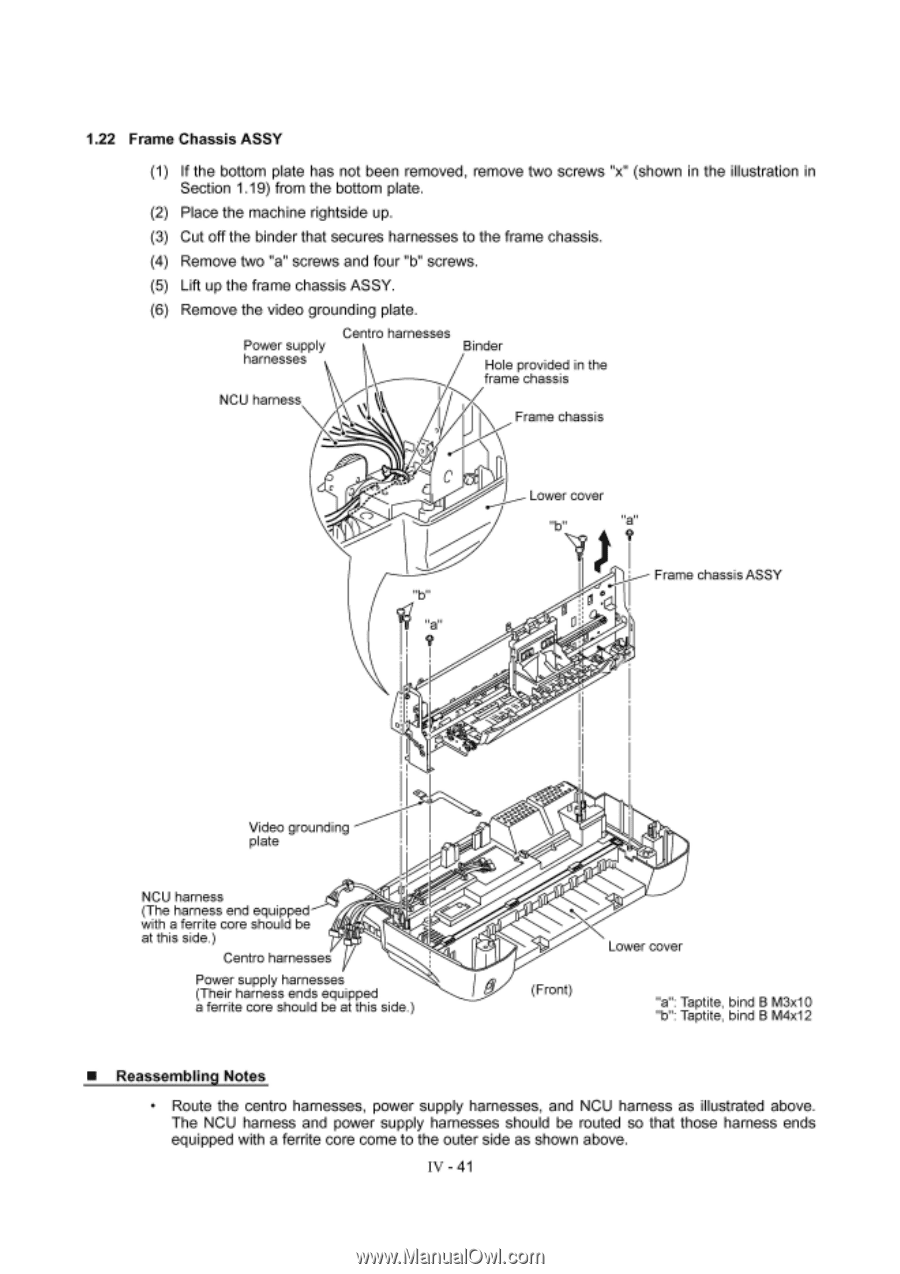
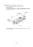
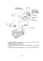
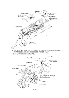
1.22 Frame Chassis ASSY (1) If the bottom plate has not been removed, remove two screws "x" (shown in the illustration in Section 1.19) from the bottom plate. (2) Place the machine rightside up. (3) Cut off the binder that secures harnesses to the frame chassis. (4) Remove two "a" screws and four "b" screws. (5) Lift up the frame chassis ASSY. (6) Remove the video grounding plate. Power supply harnesses NCU harness Centro harnesses Binder Hole provided in the frame chassis I\ Frame chassis "a" I ? I 0 Lower cover ? Frame chassis ASSY Video grounding plate NCU harness (The harness end equipped with a ferrite core should be at this side.) Centro harnesses Power supply harnesses (Their harness ends equipped a ferrite core should be at this side.) 40- Lower cover I® (Front) "a": Taptite, bind B M3x10 "b": Taptite, bind B M4x12 ■ Reassembling Notes • Route the centro harnesses, power supply harnesses, and NCU harness as illustrated above. The NCU harness and power supply harnesses should be routed so that those harness ends equipped with a ferrite core come to the outer side as shown above. IV - 41
-
 1
1 -
2
-
3
-
4
-
5
-
6
-
7
-
8
-
9
-
10
-
11
-
12
-
13
-
14
-
15
-
16
-
17
-
18
-
19
-
20
-
21
-
22
-
23
-
24
-
25
-
26
-
27
-
28
-
29
-
30
-
31
-
32
-
33
-
34
-
35
-
36
-
37
-
38
-
39
-
40
-
41
-
42
-
43
-
44
-
45
-
46
-
47
-
48
-
49
-
50
-
51
-
52
-
53
-
54
-
55
-
56
-
57
-
58
-
59
-
60
-
61
-
62
-
63
-
64
-
65
-
66
-
67
-
 68
68 -
 69
69 -
 70
70 -
 71
71 -
 72
72 -
 73
73 -
 74
74 -
 75
75 -
 76
76 -
 77
77 -
 78
78 -
79
-
80
-
81
-
82
-
83
-
84
-
85
-
86
-
87
-
88
-
89
-
90
-
91
-
92
-
93
-
94
-
95
-
96
-
97
-
98
-
99
-
100
-
101
-
102
-
103
-
104
-
105
-
106
-
107
-
108
-
109
-
110
-
111
-
112
-
113
-
114
-
115
-
116
-
117
-
118
-
119
-
120
-
121
-
122
-
123
-
124
-
125
-
126
-
127
-
128
-
129
-
130
-
131
-
132
-
133
-
134
-
135
-
136
-
137
-
138
-
139
-
140
-
141
-
142
-
143
 |
 |