Brother International MFC-7050C Service Manual - Page 60
components
 |
View all Brother International MFC-7050C manuals
Add to My Manuals
Save this manual to your list of manuals |
Page 60 highlights
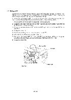
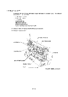
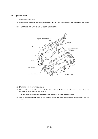
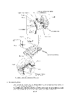
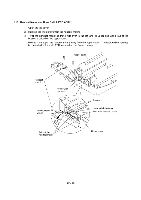
• When securing the hinge L, route the panel-main harness and CIS harness as illustrated on the previous page, taking care not to pinch them between the hinge and top cover. • When securing the hinge R, route the two grounding wires as illustrated on the previous page. • If the stopper shaft has worked out of the hinge (R or L), assemble the hinge components so that the end of the compression spring comes to the rear side of the cam follower as shown below. Stopper shaft End of the spring Cam follower Compression spring End of the spring in a wrong position 74; 7-7-N77N. Side view Cam follower Rear view ( End of the spring in a correct positior Hinge Compression spring 0 0 IV - 28
-
 1
1 -
2
-
3
-
4
-
5
-
6
-
7
-
8
-
9
-
10
-
11
-
12
-
13
-
14
-
15
-
16
-
17
-
18
-
19
-
20
-
21
-
22
-
23
-
24
-
25
-
26
-
27
-
28
-
29
-
30
-
31
-
32
-
33
-
34
-
35
-
36
-
37
-
38
-
39
-
40
-
41
-
42
-
43
-
44
-
45
-
46
-
47
-
48
-
49
-
50
-
51
-
52
-
53
-
54
-
 55
55 -
 56
56 -
 57
57 -
 58
58 -
 59
59 -
 60
60 -
 61
61 -
 62
62 -
 63
63 -
 64
64 -
 65
65 -
66
-
67
-
68
-
69
-
70
-
71
-
72
-
73
-
74
-
75
-
76
-
77
-
78
-
79
-
80
-
81
-
82
-
83
-
84
-
85
-
86
-
87
-
88
-
89
-
90
-
91
-
92
-
93
-
94
-
95
-
96
-
97
-
98
-
99
-
100
-
101
-
102
-
103
-
104
-
105
-
106
-
107
-
108
-
109
-
110
-
111
-
112
-
113
-
114
-
115
-
116
-
117
-
118
-
119
-
120
-
121
-
122
-
123
-
124
-
125
-
126
-
127
-
128
-
129
-
130
-
131
-
132
-
133
-
134
-
135
-
136
-
137
-
138
-
139
-
140
-
141
-
142
-
143
 |
 |

•
When
securing
the
hinge
L,
route
the
panel
-main
harness
and
CIS
harness
as
illustrated
on
the
previous
page,
taking
care
not
to
pinch
them
between
the
hinge
and
top
cover.
•
When
securing
the
hinge
R,
route
the
two
grounding
wires
as
illustrated
on
the
previous
page.
•
If
the
stopper
shaft
has
worked
out
of
the
hinge
(R
or
L),
assemble
the
hinge
components
so
that
the
end
of
the
compression
spring
comes
to
the
rear
side
of
the
cam
follower
as
shown
below.
Stopper
shaft
End
of
the
spring
Cam
follower
Compression
spring
Side
view
End
of
the
spring
in
a
wrong
position
7;
4-
77-N77N.
(
End
of
the
spring
in
a
correct
positior
Cam
follower
Rear
view
Compression
spring
Hinge
0
0
IV
-
28