Brother International MFC-7050C Service Manual - Page 71
Power, Supply, Interface, Place, bottom, plate, rightside, Remove, screws, power, supply, screw,
 |
View all Brother International MFC-7050C manuals
Add to My Manuals
Save this manual to your list of manuals |
Page 71 highlights
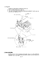
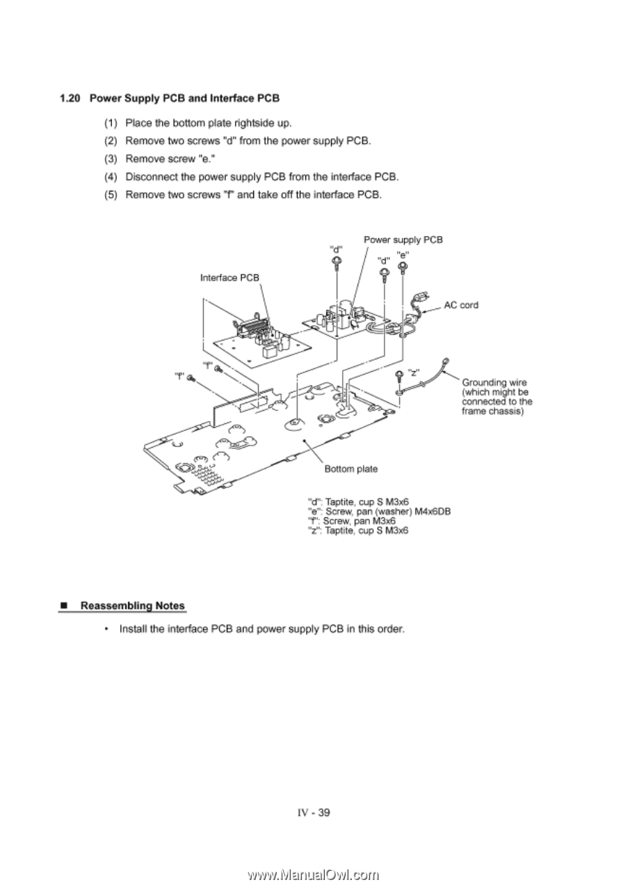
1.20 Power Supply PCB and Interface PCB (1) Place the bottom plate rightside up. (2) Remove two screws "d" from the power supply PCB. (3) Remove screw "e." (4) Disconnect the power supply PCB from the interface PCB. (5) Remove two screws "f" and take off the interface PCB. Interface PCB Power supply PCB AC cord ?„ z„ Grounding wire (which might be connected to the frame chassis) Bottom plate "d": Taptite, cup S M3x6 "e": Screw, pan (washer) M4x6DB "f": Screw, pan M3x6 "z": Taptite, cup S M3x6 ■ Reassembling Notes • Install the interface PCB and power supply PCB in this order. IV - 39
-
 1
1 -
2
-
3
-
4
-
5
-
6
-
7
-
8
-
9
-
10
-
11
-
12
-
13
-
14
-
15
-
16
-
17
-
18
-
19
-
20
-
21
-
22
-
23
-
24
-
25
-
26
-
27
-
28
-
29
-
30
-
31
-
32
-
33
-
34
-
35
-
36
-
37
-
38
-
39
-
40
-
41
-
42
-
43
-
44
-
45
-
46
-
47
-
48
-
49
-
50
-
51
-
52
-
53
-
54
-
55
-
56
-
57
-
58
-
59
-
60
-
61
-
62
-
63
-
64
-
65
-
 66
66 -
 67
67 -
 68
68 -
 69
69 -
 70
70 -
 71
71 -
 72
72 -
 73
73 -
 74
74 -
 75
75 -
 76
76 -
77
-
78
-
79
-
80
-
81
-
82
-
83
-
84
-
85
-
86
-
87
-
88
-
89
-
90
-
91
-
92
-
93
-
94
-
95
-
96
-
97
-
98
-
99
-
100
-
101
-
102
-
103
-
104
-
105
-
106
-
107
-
108
-
109
-
110
-
111
-
112
-
113
-
114
-
115
-
116
-
117
-
118
-
119
-
120
-
121
-
122
-
123
-
124
-
125
-
126
-
127
-
128
-
129
-
130
-
131
-
132
-
133
-
134
-
135
-
136
-
137
-
138
-
139
-
140
-
141
-
142
-
143
 |
 |
1.20
Power
Supply
PCB
and
Interface
PCB
(1)
Place
the
bottom
plate
rightside
up.
(2)
Remove
two
screws
"d"
from
the
power
supply
PCB.
(3)
Remove
screw
"e."
(4)
Disconnect
the
power
supply
PCB
from
the
interface
PCB.
(5)
Remove
two
screws
"f"
and
take
off
the
interface
PCB.
Power
supply
PCB
Interface
PCB
AC
cord
?„
z
„
Bottom
plate
"d":
Taptite,
cup
S
M3x6
"e":
Screw,
pan
(washer)
M4x6DB
"f":
Screw,
pan
M3x6
"z":
Taptite,
cup
S
M3x6
■
Reassembling
Notes
•
Install
the
interface
PCB
and
power
supply
PCB
in
this
order.
IV
-
39
Grounding wire
(which
might
be
connected
to
the
frame
chassis)