Brother International MFC-7050C Service Manual - Page 42
Brother International MFC-7050C Manual
 |
View all Brother International MFC-7050C manuals
Add to My Manuals
Save this manual to your list of manuals |
Page 42 highlights
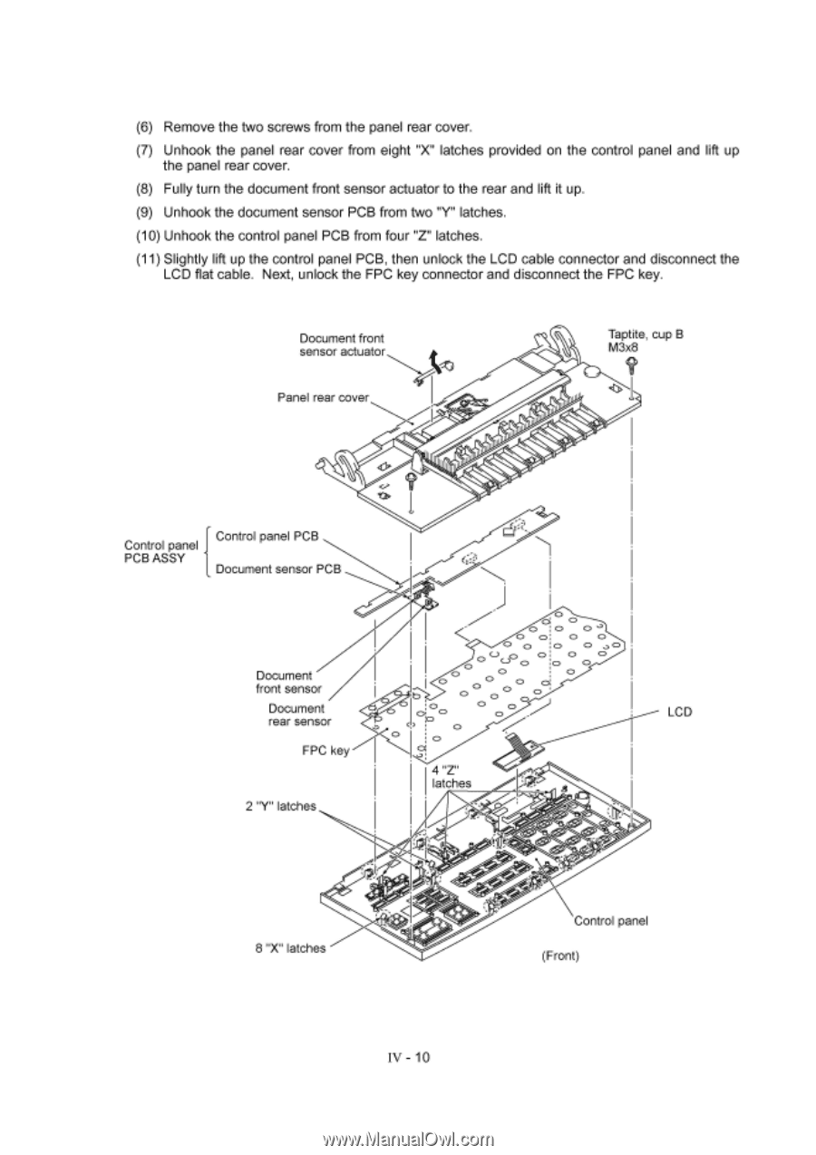
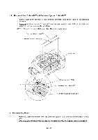
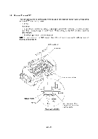
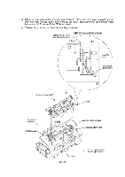
(6) Remove the two screws from the panel rear cover. (7) Unhook the panel rear cover from eight "X" latches provided on the control panel and lift up the panel rear cover. (8) Fully turn the document front sensor actuator to the rear and lift it up. (9) Unhook the document sensor PCB from two "Y" latches. (10) Unhook the control panel PCB from four "Z" latches. (11) Slightly lift up the control panel PCB, then unlock the LCD cable connector and disconnect the LCD flat cable. Next, unlock the FPC key connector and disconnect the FPC key. Document front sensor actuator Panel rear cover Taptite, cup B M3x8 Control panel Control panel PCB PCB ASSY Document sensor PCB Document front sensor Document rear sensor FPC key 2 "Y" latches O O b 0 0, 0 0 CD 0 4 "Z" latches O 0 O 0 0 O O O O (_) CD O C> CD co, 0 O O O O LCD 5O- 8 "X" latches Control panel (Front) - 10
-
 1
1 -
2
-
3
-
4
-
5
-
6
-
7
-
8
-
9
-
10
-
11
-
12
-
13
-
14
-
15
-
16
-
17
-
18
-
19
-
20
-
21
-
22
-
23
-
24
-
25
-
26
-
27
-
28
-
29
-
30
-
31
-
32
-
33
-
34
-
35
-
36
-
 37
37 -
 38
38 -
 39
39 -
 40
40 -
 41
41 -
 42
42 -
 43
43 -
 44
44 -
 45
45 -
 46
46 -
 47
47 -
48
-
49
-
50
-
51
-
52
-
53
-
54
-
55
-
56
-
57
-
58
-
59
-
60
-
61
-
62
-
63
-
64
-
65
-
66
-
67
-
68
-
69
-
70
-
71
-
72
-
73
-
74
-
75
-
76
-
77
-
78
-
79
-
80
-
81
-
82
-
83
-
84
-
85
-
86
-
87
-
88
-
89
-
90
-
91
-
92
-
93
-
94
-
95
-
96
-
97
-
98
-
99
-
100
-
101
-
102
-
103
-
104
-
105
-
106
-
107
-
108
-
109
-
110
-
111
-
112
-
113
-
114
-
115
-
116
-
117
-
118
-
119
-
120
-
121
-
122
-
123
-
124
-
125
-
126
-
127
-
128
-
129
-
130
-
131
-
132
-
133
-
134
-
135
-
136
-
137
-
138
-
139
-
140
-
141
-
142
-
143
 |
 |