Brother International MFC-7050C Service Manual - Page 20
completion
 |
View all Brother International MFC-7050C manuals
Add to My Manuals
Save this manual to your list of manuals |
Page 20 highlights
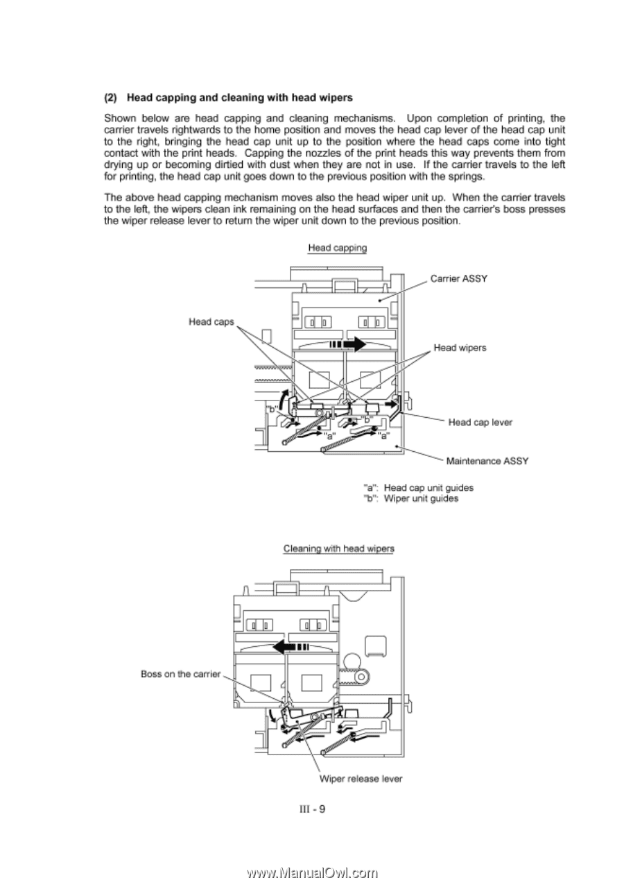
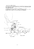
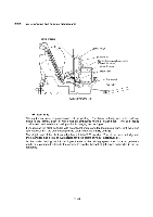
(2) Head capping and cleaning with head wipers Shown below are head capping and cleaning mechanisms. Upon completion of printing, the carrier travels rightwards to the home position and moves the head cap lever of the head cap unit to the right, bringing the head cap unit up to the position where the head caps come into tight contact with the print heads. Capping the nozzles of the print heads this way prevents them from drying up or becoming dirtied with dust when they are not in use. If the carrier travels to the left for printing, the head cap unit goes down to the previous position with the springs. The above head capping mechanism moves also the head wiper unit up. When the carrier travels to the left, the wipers clean ink remaining on the head surfaces and then the carrier's boss presses the wiper release lever to return the wiper unit down to the previous position. Head capping Carrier ASSY Head caps I III Head wipers Boss on the carrier 0 Head cap lever Maintenance ASSY "a": Head cap unit guides "b": Wiper unit guides Cleaning with head wipers ff ( ss• Wiper release lever III - 9
-
 1
1 -
2
-
3
-
4
-
5
-
6
-
7
-
8
-
9
-
10
-
11
-
12
-
13
-
14
-
 15
15 -
 16
16 -
 17
17 -
 18
18 -
 19
19 -
 20
20 -
 21
21 -
 22
22 -
 23
23 -
 24
24 -
 25
25 -
26
-
27
-
28
-
29
-
30
-
31
-
32
-
33
-
34
-
35
-
36
-
37
-
38
-
39
-
40
-
41
-
42
-
43
-
44
-
45
-
46
-
47
-
48
-
49
-
50
-
51
-
52
-
53
-
54
-
55
-
56
-
57
-
58
-
59
-
60
-
61
-
62
-
63
-
64
-
65
-
66
-
67
-
68
-
69
-
70
-
71
-
72
-
73
-
74
-
75
-
76
-
77
-
78
-
79
-
80
-
81
-
82
-
83
-
84
-
85
-
86
-
87
-
88
-
89
-
90
-
91
-
92
-
93
-
94
-
95
-
96
-
97
-
98
-
99
-
100
-
101
-
102
-
103
-
104
-
105
-
106
-
107
-
108
-
109
-
110
-
111
-
112
-
113
-
114
-
115
-
116
-
117
-
118
-
119
-
120
-
121
-
122
-
123
-
124
-
125
-
126
-
127
-
128
-
129
-
130
-
131
-
132
-
133
-
134
-
135
-
136
-
137
-
138
-
139
-
140
-
141
-
142
-
143
 |
 |