Brother International MFC-7050C Service Manual - Page 51
cutout provided
 |
View all Brother International MFC-7050C manuals
Add to My Manuals
Save this manual to your list of manuals |
Page 51 highlights
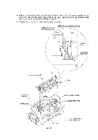
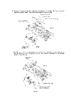
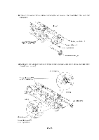
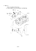
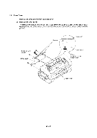
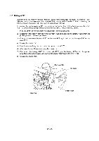
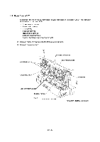
■ Reassembling Notes • When reinstalling the scanner motor, fit it in the latch provided on the scanner frame with the connector facing up and then secure it with the screw. (See page IV-16.) • When setting the scanner frame ASSY back into place, - secure the grounding terminals to the scanner frame ASSY with the screws at an angle shown on page IV-15. - route the CIS harness through the scanner frame ASSY (or connect the CIS harness to the CIS unit if mounted), - route the panel-main harness through the cutout provided in the scanner frame ASSY. • When reinstalling the CIS unit, first connect the CIS harness, insert the left end under the arm of the scanner frame, put the CIS unit into the scanner frame, and move it to right (see the illustration given on page IV-14). • When attaching the CIS film, align the right, left and rear edges of the cutout with those provided in the scanner frame and fit its two tabs into the scanner frame, as illustrated on page IV-13 • Once removed, the shield film and CIS film become unusable and new parts will have to be put back in. IV - 19
-
 1
1 -
2
-
3
-
4
-
5
-
6
-
7
-
8
-
9
-
10
-
11
-
12
-
13
-
14
-
15
-
16
-
17
-
18
-
19
-
20
-
21
-
22
-
23
-
24
-
25
-
26
-
27
-
28
-
29
-
30
-
31
-
32
-
33
-
34
-
35
-
36
-
37
-
38
-
39
-
40
-
41
-
42
-
43
-
44
-
45
-
 46
46 -
 47
47 -
 48
48 -
 49
49 -
 50
50 -
 51
51 -
 52
52 -
 53
53 -
 54
54 -
 55
55 -
 56
56 -
57
-
58
-
59
-
60
-
61
-
62
-
63
-
64
-
65
-
66
-
67
-
68
-
69
-
70
-
71
-
72
-
73
-
74
-
75
-
76
-
77
-
78
-
79
-
80
-
81
-
82
-
83
-
84
-
85
-
86
-
87
-
88
-
89
-
90
-
91
-
92
-
93
-
94
-
95
-
96
-
97
-
98
-
99
-
100
-
101
-
102
-
103
-
104
-
105
-
106
-
107
-
108
-
109
-
110
-
111
-
112
-
113
-
114
-
115
-
116
-
117
-
118
-
119
-
120
-
121
-
122
-
123
-
124
-
125
-
126
-
127
-
128
-
129
-
130
-
131
-
132
-
133
-
134
-
135
-
136
-
137
-
138
-
139
-
140
-
141
-
142
-
143
 |
 |