Brother International MFC-7050C Service Manual - Page 69
Disassemble
 |
View all Brother International MFC-7050C manuals
Add to My Manuals
Save this manual to your list of manuals |
Page 69 highlights
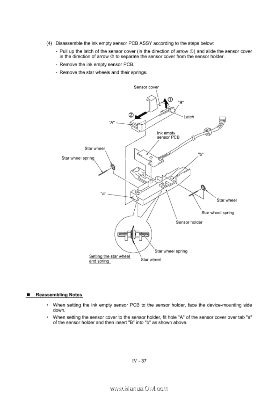
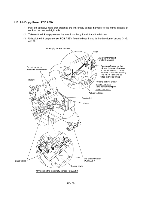
(4) Disassemble the ink empty sensor PCB ASSY according to the steps below: - Pull up the latch of the sensor cover (in the direction of arrow 0) and slide the sensor cover in the direction of arrow 0 to separate the sensor cover from the sensor holder. - Remove the ink empty sensor PCB. - Remove the star wheels and their springs. Sensor cover "B" Latch Star wheel Star wheel spring Ink empty sensor PCB Star wheel Star wheel spring Sensor holder Setting the star wheel and spring Star wheel spring Star wheel ■ Reassembling Notes • When setting the ink empty sensor PCB to the sensor holder, face the device-mounting side down. • When setting the sensor cover to the sensor holder, fit hole "A" of the sensor cover over tab "a" of the sensor holder and then insert "B" into "b" as shown above. IV - 37
-
 1
1 -
2
-
3
-
4
-
5
-
6
-
7
-
8
-
9
-
10
-
11
-
12
-
13
-
14
-
15
-
16
-
17
-
18
-
19
-
20
-
21
-
22
-
23
-
24
-
25
-
26
-
27
-
28
-
29
-
30
-
31
-
32
-
33
-
34
-
35
-
36
-
37
-
38
-
39
-
40
-
41
-
42
-
43
-
44
-
45
-
46
-
47
-
48
-
49
-
50
-
51
-
52
-
53
-
54
-
55
-
56
-
57
-
58
-
59
-
60
-
61
-
62
-
63
-
 64
64 -
 65
65 -
 66
66 -
 67
67 -
 68
68 -
 69
69 -
 70
70 -
 71
71 -
 72
72 -
 73
73 -
 74
74 -
75
-
76
-
77
-
78
-
79
-
80
-
81
-
82
-
83
-
84
-
85
-
86
-
87
-
88
-
89
-
90
-
91
-
92
-
93
-
94
-
95
-
96
-
97
-
98
-
99
-
100
-
101
-
102
-
103
-
104
-
105
-
106
-
107
-
108
-
109
-
110
-
111
-
112
-
113
-
114
-
115
-
116
-
117
-
118
-
119
-
120
-
121
-
122
-
123
-
124
-
125
-
126
-
127
-
128
-
129
-
130
-
131
-
132
-
133
-
134
-
135
-
136
-
137
-
138
-
139
-
140
-
141
-
142
-
143
 |
 |