Brother International MFC-7050C Service Manual - Page 78
Brother International MFC-7050C Manual
 |
View all Brother International MFC-7050C manuals
Add to My Manuals
Save this manual to your list of manuals |
Page 78 highlights
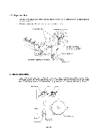
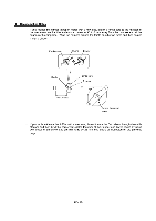
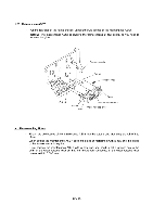
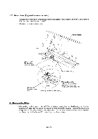
■ Reassembling Notes • If you replace the carrier transport motor with a new one, attach a ferrite core to the harness of the new motor so that the ferrite core comes to 30 ±10 mm away from the harness end at the connector housing side. Wind the harness around the ferrite core by two turns and then secure it with a binder. Ferrite core 2 turns Binder .., Binder Ferrite core 2 turns ./ O 30 ± 10 mm @ O Carrier transport motor • If you replace the carrier ASSY with a new one, thread the carrier flat cables through the cable stopper and then bind the carrier flat cables together at their upper and lower edges by using two pieces of adhesive tape (15 mm wide by 25 mm long each) as illustrated on the previous page. IV - 46
-
 1
1 -
2
-
3
-
4
-
5
-
6
-
7
-
8
-
9
-
10
-
11
-
12
-
13
-
14
-
15
-
16
-
17
-
18
-
19
-
20
-
21
-
22
-
23
-
24
-
25
-
26
-
27
-
28
-
29
-
30
-
31
-
32
-
33
-
34
-
35
-
36
-
37
-
38
-
39
-
40
-
41
-
42
-
43
-
44
-
45
-
46
-
47
-
48
-
49
-
50
-
51
-
52
-
53
-
54
-
55
-
56
-
57
-
58
-
59
-
60
-
61
-
62
-
63
-
64
-
65
-
66
-
67
-
68
-
69
-
70
-
71
-
72
-
 73
73 -
 74
74 -
 75
75 -
 76
76 -
 77
77 -
 78
78 -
 79
79 -
 80
80 -
 81
81 -
 82
82 -
 83
83 -
84
-
85
-
86
-
87
-
88
-
89
-
90
-
91
-
92
-
93
-
94
-
95
-
96
-
97
-
98
-
99
-
100
-
101
-
102
-
103
-
104
-
105
-
106
-
107
-
108
-
109
-
110
-
111
-
112
-
113
-
114
-
115
-
116
-
117
-
118
-
119
-
120
-
121
-
122
-
123
-
124
-
125
-
126
-
127
-
128
-
129
-
130
-
131
-
132
-
133
-
134
-
135
-
136
-
137
-
138
-
139
-
140
-
141
-
142
-
143
 |
 |

■
Reassembling
Notes
•
If
you
replace
the
carrier
transport
motor
with
a
new
one,
attach
a
ferrite
core
to
the
harness
of
the
new
motor
so
that
the
ferrite
core
comes
to
30
±10
mm
away
from
the
harness
end
at
the
connector
housing
side.
Wind
the
harness
around
the
ferrite
core
by
two
turns
and
then
secure
it
with
a
binder.
Ferrite
core
Binder
2
turns
Binder
30
±
10
mm
..,
Ferrite
core
2
turns
./
@
O
O
Carrier
transport
motor
•
If
you
replace
the
carrier
ASSY
with
a
new
one,
thread
the
carrier
flat
cables
through
the
cable
stopper
and
then
bind
the
carrier
flat
cables
together
at
their
upper
and
lower
edges
by
using
two
pieces
of
adhesive
tape
(15
mm
wide
by
25
mm
long
each)
as
illustrated
on
the
previous
page.
IV
-
46