Brother International MFC-7050C Service Manual - Page 62
screwdriver.
 |
View all Brother International MFC-7050C manuals
Add to My Manuals
Save this manual to your list of manuals |
Page 62 highlights
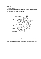
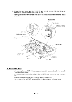
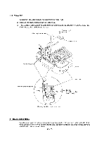
(4) Disassemble the handset mount by unhooking two latches "a" of the upper handset mount with a flat screwdriver. (5) Remove the hook switch PCB ASSY by unhooking latch "b." (6) Disconnect the hook switch harness from the hook switch PCB. Upper handset mount Lower handset mount ,?, .41 70' Latch "a" Latch "a" Hook switch PCB ASSY Latch "b" Upper cover Hook switch harness Through the cutout Hook switch harness --------7 Route underneath the hook switch PCB Routing of the hook switch harness • Reassembling Notes • When assembling the upper and lower handset mounts, route the hook switch harness underneath the hook switch PCB and through the cutout as shown above. Take care not to pinch the harness between the upper and lower mounts. IV - 30
-
 1
1 -
2
-
3
-
4
-
5
-
6
-
7
-
8
-
9
-
10
-
11
-
12
-
13
-
14
-
15
-
16
-
17
-
18
-
19
-
20
-
21
-
22
-
23
-
24
-
25
-
26
-
27
-
28
-
29
-
30
-
31
-
32
-
33
-
34
-
35
-
36
-
37
-
38
-
39
-
40
-
41
-
42
-
43
-
44
-
45
-
46
-
47
-
48
-
49
-
50
-
51
-
52
-
53
-
54
-
55
-
56
-
 57
57 -
 58
58 -
 59
59 -
 60
60 -
 61
61 -
 62
62 -
 63
63 -
 64
64 -
 65
65 -
 66
66 -
 67
67 -
68
-
69
-
70
-
71
-
72
-
73
-
74
-
75
-
76
-
77
-
78
-
79
-
80
-
81
-
82
-
83
-
84
-
85
-
86
-
87
-
88
-
89
-
90
-
91
-
92
-
93
-
94
-
95
-
96
-
97
-
98
-
99
-
100
-
101
-
102
-
103
-
104
-
105
-
106
-
107
-
108
-
109
-
110
-
111
-
112
-
113
-
114
-
115
-
116
-
117
-
118
-
119
-
120
-
121
-
122
-
123
-
124
-
125
-
126
-
127
-
128
-
129
-
130
-
131
-
132
-
133
-
134
-
135
-
136
-
137
-
138
-
139
-
140
-
141
-
142
-
143
 |
 |

(4)
Disassemble
the
handset
mount
by
unhooking
two
latches
"a"
of
the
upper
handset
mount
with
a
flat
screwdriver.
(5)
Remove
the
hook
switch
PCB
ASSY
by
unhooking
latch
"b."
(6)
Disconnect
the
hook
switch
harness
from
the
hook
switch
PCB.
,?,
Upper
handset
mount
.41
7
0
'
Latch
"a"
Latch
"a"
Lower
handset
mount
Upper
cover
Hook
switch
harness
Hook
switch
PCB
ASSY
Latch
"b"
Through
the
cutout
Hook
switch
harness
----
----7
Route
underneath
the
hook
switch
PCB
Routing
of
the
hook
switch
harness
•
Reassembling
Notes
•
When
assembling
the
upper
and
lower
handset
mounts,
route
the
hook
switch
harness
underneath
the
hook
switch
PCB
and
through
the
cutout
as
shown
above.
Take
care
not
to
pinch
the
harness
between
the
upper
and
lower
mounts.
IV
-
30