Brother International MFC-7050C Service Manual - Page 100
Detailed, Description Of, Maintenance, Functions
 |
View all Brother International MFC-7050C manuals
Add to My Manuals
Save this manual to your list of manuals |
Page 100 highlights
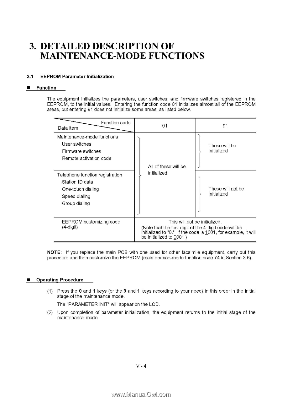
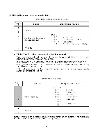
3. DETAILED DESCRIPTION OF MAINTENANCE-MODE FUNCTIONS 3.1 EEPROM Parameter Initialization ■ Function The equipment initializes the parameters, user switches, and firmware switches registered in the EEPROM, to the initial values. Entering the function code 01 initializes almost all of the EEPROM areas, but entering 91 does not initialize some areas, as listed below. Data item Function code Maintenance-mode functions User switches Firmware switches Remote activation code Telephone function registration Station ID data One-touch dialing Speed dialing Group dialing 01 All of these will be. ›- initialized 91 These will be I initialized 1 These will not be initialized ,- EEPROM customizing code (4-digit) This will not be initialized. (Note that the first digit of the 4-digit code will be initialized to "0." If the code is 1001, for example, it will be initialized to 0001.) NOTE: If you replace the main PCB with one used for other facsimile equipment, carry out this procedure and then customize the EEPROM (maintenance-mode function code 74 in Section 3.6). ■ Operating Procedure (1) Press the 0 and 1 keys (or the 9 and 1 keys according to your need) in this order in the initial stage of the maintenance mode. The "PARAMETER INIT" will appear on the LCD. (2) Upon completion of parameter initialization, the equipment returns to the initial stage of the maintenance mode. V - 4
-
 1
1 -
2
-
3
-
4
-
5
-
6
-
7
-
8
-
9
-
10
-
11
-
12
-
13
-
14
-
15
-
16
-
17
-
18
-
19
-
20
-
21
-
22
-
23
-
24
-
25
-
26
-
27
-
28
-
29
-
30
-
31
-
32
-
33
-
34
-
35
-
36
-
37
-
38
-
39
-
40
-
41
-
42
-
43
-
44
-
45
-
46
-
47
-
48
-
49
-
50
-
51
-
52
-
53
-
54
-
55
-
56
-
57
-
58
-
59
-
60
-
61
-
62
-
63
-
64
-
65
-
66
-
67
-
68
-
69
-
70
-
71
-
72
-
73
-
74
-
75
-
76
-
77
-
78
-
79
-
80
-
81
-
82
-
83
-
84
-
85
-
86
-
87
-
88
-
89
-
90
-
91
-
92
-
93
-
94
-
 95
95 -
 96
96 -
 97
97 -
 98
98 -
 99
99 -
 100
100 -
 101
101 -
 102
102 -
 103
103 -
 104
104 -
 105
105 -
106
-
107
-
108
-
109
-
110
-
111
-
112
-
113
-
114
-
115
-
116
-
117
-
118
-
119
-
120
-
121
-
122
-
123
-
124
-
125
-
126
-
127
-
128
-
129
-
130
-
131
-
132
-
133
-
134
-
135
-
136
-
137
-
138
-
139
-
140
-
141
-
142
-
143
 |
 |