Brother International MFC-7050C Service Manual - Page 25
Brother International MFC-7050C Manual
 |
View all Brother International MFC-7050C manuals
Add to My Manuals
Save this manual to your list of manuals |
Page 25 highlights
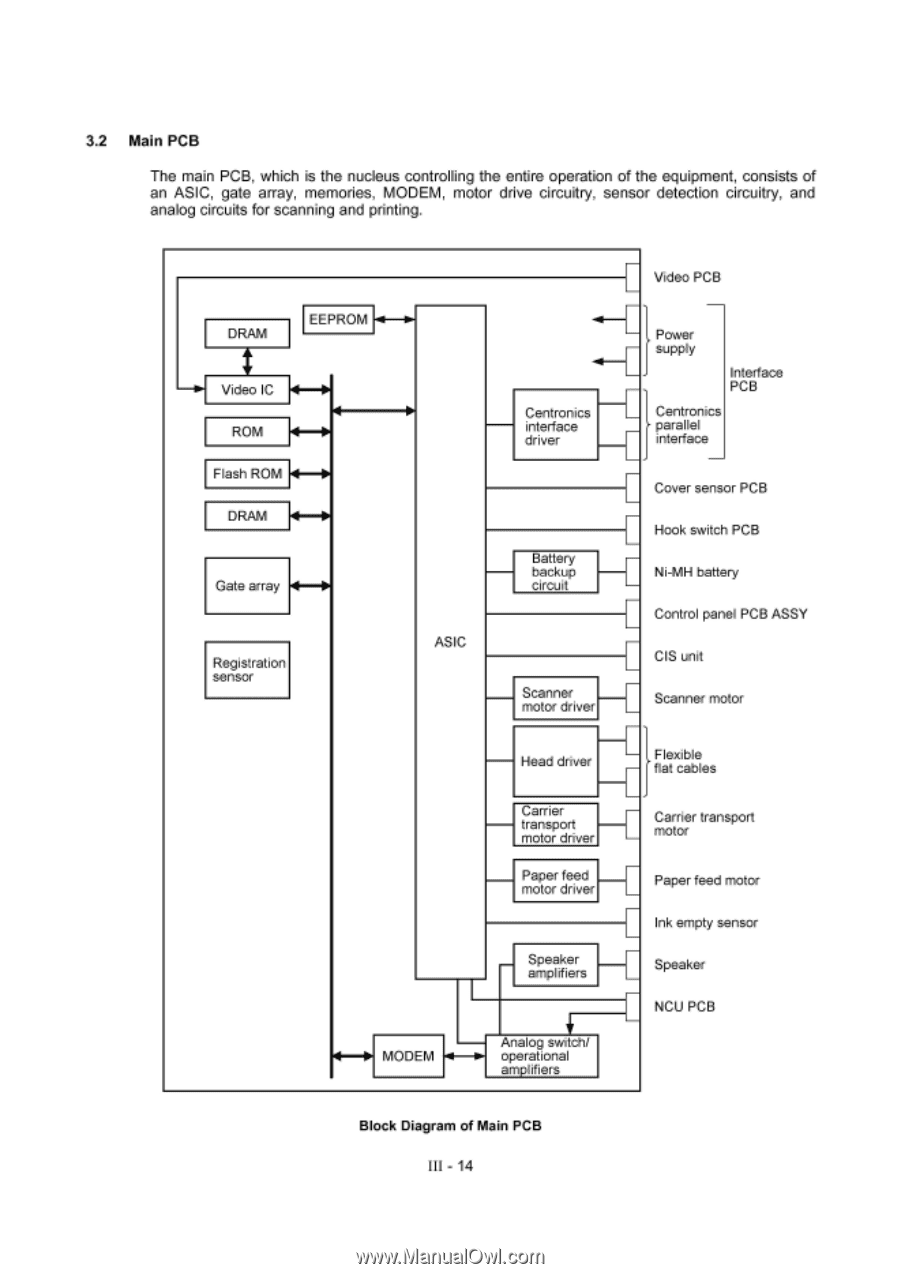
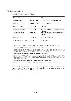
3.2 Main PCB The main PCB, which is the nucleus controlling the entire operation of the equipment, consists of an ASIC, gate array, memories, MODEM, motor drive circuitry, sensor detection circuitry, and analog circuits for scanning and printing. DRAM EEPROM 411-11IP- H HIP Video IC ROM HP' Flash ROM F1-10 DRAM I4-• Gate array Registration sensor ASIC i Video PCB -4-1 Power 1, supply Interface Centronics interface driver L PCB Centronics parallel L ., interface I Cover sensor PCB Battery backup circuit I Hook switch PCB I Ni-MH battery I Control panel PCB ASSY I CIS unit Scanner motor driver Head driver I Scanner motor I Flexible I :flat cables Carrier transport motor driver Paper feed motor driver Speaker amplifiers Analog switch/ MODEM -011-0. operational amplifiers Carrier transport I motor I Paper feed motor I Ink empty sensor L Speaker I NCU PCB Block Diagram of Main PCB III - 14
-
 1
1 -
2
-
3
-
4
-
5
-
6
-
7
-
8
-
9
-
10
-
11
-
12
-
13
-
14
-
15
-
16
-
17
-
18
-
19
-
 20
20 -
 21
21 -
 22
22 -
 23
23 -
 24
24 -
 25
25 -
 26
26 -
 27
27 -
 28
28 -
 29
29 -
 30
30 -
31
-
32
-
33
-
34
-
35
-
36
-
37
-
38
-
39
-
40
-
41
-
42
-
43
-
44
-
45
-
46
-
47
-
48
-
49
-
50
-
51
-
52
-
53
-
54
-
55
-
56
-
57
-
58
-
59
-
60
-
61
-
62
-
63
-
64
-
65
-
66
-
67
-
68
-
69
-
70
-
71
-
72
-
73
-
74
-
75
-
76
-
77
-
78
-
79
-
80
-
81
-
82
-
83
-
84
-
85
-
86
-
87
-
88
-
89
-
90
-
91
-
92
-
93
-
94
-
95
-
96
-
97
-
98
-
99
-
100
-
101
-
102
-
103
-
104
-
105
-
106
-
107
-
108
-
109
-
110
-
111
-
112
-
113
-
114
-
115
-
116
-
117
-
118
-
119
-
120
-
121
-
122
-
123
-
124
-
125
-
126
-
127
-
128
-
129
-
130
-
131
-
132
-
133
-
134
-
135
-
136
-
137
-
138
-
139
-
140
-
141
-
142
-
143
 |
 |