Brother International MFC-7050C Service Manual - Page 59
illustrated
 |
View all Brother International MFC-7050C manuals
Add to My Manuals
Save this manual to your list of manuals |
Page 59 highlights
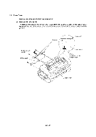
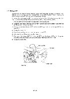
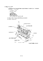
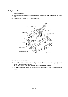
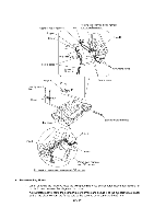
Scanner motor harness Support Binder Routing the scanner motor harness Slot and grounding wires Hinge R 50 ± 5 mm Ferrite cores Approx. 30 mm Hinge R 9 Taptite, bind B M4x12 9 9 Hinge L 91' II Grounding wires Ferrite cores Top cover Scanner motor harness Hinge L Cutout Binder Panel-main harness and CIS harness Routing the panel-main harness and CIS harness • Reassembling Notes • When securing the hinge R, route the two grounding wires as illustrated above, taking care not to pinch them between the hinge and top cover. • As illustrated above, route the scanner motor harness and secure it to the support with a binder so that the distance from the ferrite core to the secured point comes to 50 ±5 mm. IV - 27
-
 1
1 -
2
-
3
-
4
-
5
-
6
-
7
-
8
-
9
-
10
-
11
-
12
-
13
-
14
-
15
-
16
-
17
-
18
-
19
-
20
-
21
-
22
-
23
-
24
-
25
-
26
-
27
-
28
-
29
-
30
-
31
-
32
-
33
-
34
-
35
-
36
-
37
-
38
-
39
-
40
-
41
-
42
-
43
-
44
-
45
-
46
-
47
-
48
-
49
-
50
-
51
-
52
-
53
-
 54
54 -
 55
55 -
 56
56 -
 57
57 -
 58
58 -
 59
59 -
 60
60 -
 61
61 -
 62
62 -
 63
63 -
 64
64 -
65
-
66
-
67
-
68
-
69
-
70
-
71
-
72
-
73
-
74
-
75
-
76
-
77
-
78
-
79
-
80
-
81
-
82
-
83
-
84
-
85
-
86
-
87
-
88
-
89
-
90
-
91
-
92
-
93
-
94
-
95
-
96
-
97
-
98
-
99
-
100
-
101
-
102
-
103
-
104
-
105
-
106
-
107
-
108
-
109
-
110
-
111
-
112
-
113
-
114
-
115
-
116
-
117
-
118
-
119
-
120
-
121
-
122
-
123
-
124
-
125
-
126
-
127
-
128
-
129
-
130
-
131
-
132
-
133
-
134
-
135
-
136
-
137
-
138
-
139
-
140
-
141
-
142
-
143
 |
 |

Routing
the
scanner
motor
harness
Scanner
motor
harness
Slot
and
grounding
wires
Support
Binder
Ferrite
cores
Hinge
R
Taptite,
bind
B
M4x12
9
Hinge
L
Hinge
L
9
Top
cover
50
±
5
mm
Approx.
30
mm
9
91‘
I I
Ferrite
cores
Cutout
Binder
Panel
-main
harness
and
CIS
harness
Routing
the
panel
-main
harness
and
CIS
harness
•
Reassembling
Notes
Hinge
R
Grounding
wires
Scanner
motor
harness
•
When
securing
the
hinge
R,
route
the
two
grounding
wires
as
illustrated
above,
taking
care
not
to
pinch
them
between
the
hinge
and
top
cover.
•
As
illustrated
above,
route
the
scanner
motor
harness
and
secure
it
to
the
support
with
a
binder
so
that
the
distance
from
the
ferrite
core
to
the
secured
point
comes
to
50
±5
mm.
IV
-
27