Brother International MFC-7050C Service Manual - Page 30
Brother International MFC-7050C Manual
 |
View all Brother International MFC-7050C manuals
Add to My Manuals
Save this manual to your list of manuals |
Page 30 highlights
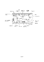
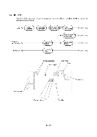
3.6 Interface PCB This PCB interfaces the main PCB and the externally connected computer with each other. The interface PCB also generates +22V and +11.75V supplies from the +30V source and +3.3V supply from the +5V source, and then feeds them to the main PCB. The +22V and +11.75V sources are stabilized and fed to the thermal ink-jet print heads embedded in the ink cartridges and the head driver IC on the main PCB. The +3.3V source is stabilized and fed to the ASIC and MODEM on the main PCB. As shown below, the +22V source may be turned on or off by control signals issued from the main PCB. Interface PCB Centronics I/F connector Main PCB +30V O +5V O 22V regulation circuit 11.75V regulation circuit 3.3V regulation circuit Interface Circuit O +30V < 22V control signal O +22V O +11.75V O +5V O +3.3V Ill - 19
-
 1
1 -
2
-
3
-
4
-
5
-
6
-
7
-
8
-
9
-
10
-
11
-
12
-
13
-
14
-
15
-
16
-
17
-
18
-
19
-
20
-
21
-
22
-
23
-
24
-
 25
25 -
 26
26 -
 27
27 -
 28
28 -
 29
29 -
 30
30 -
 31
31 -
 32
32 -
 33
33 -
 34
34 -
 35
35 -
36
-
37
-
38
-
39
-
40
-
41
-
42
-
43
-
44
-
45
-
46
-
47
-
48
-
49
-
50
-
51
-
52
-
53
-
54
-
55
-
56
-
57
-
58
-
59
-
60
-
61
-
62
-
63
-
64
-
65
-
66
-
67
-
68
-
69
-
70
-
71
-
72
-
73
-
74
-
75
-
76
-
77
-
78
-
79
-
80
-
81
-
82
-
83
-
84
-
85
-
86
-
87
-
88
-
89
-
90
-
91
-
92
-
93
-
94
-
95
-
96
-
97
-
98
-
99
-
100
-
101
-
102
-
103
-
104
-
105
-
106
-
107
-
108
-
109
-
110
-
111
-
112
-
113
-
114
-
115
-
116
-
117
-
118
-
119
-
120
-
121
-
122
-
123
-
124
-
125
-
126
-
127
-
128
-
129
-
130
-
131
-
132
-
133
-
134
-
135
-
136
-
137
-
138
-
139
-
140
-
141
-
142
-
143
 |
 |
