Brother International MFC-7050C Service Manual - Page 116
EEPROM, Customizing
 |
View all Brother International MFC-7050C manuals
Add to My Manuals
Save this manual to your list of manuals |
Page 116 highlights
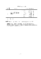
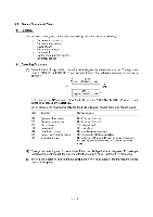
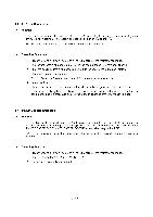
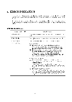
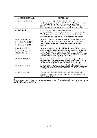
3.6 EEPROM Customizing ■ Function This function allows you to customize the EEPROM according to language, function settings, and firmware switch settings. The customizing codes list is given in Appendix 1. NOTE: If you replace the main PCB, be sure to carry out this procedure. ■ Operating Procedure (1) Press the 7 and 4 keys in this order in the initial stage of the maintenance mode. The current customizing code (e.g., 1001 in the case of the U.S.A. versions) appears. (2) Enter the desired customizing code (e.g., 0002 in the case of the Canadian versions). The newly entered code appears. NOTE: If a wrong 4-digit code is entered, the equipment will malfunction. (3) Press the Start key. The equipment saves the setting and returns to the initial stage of the maintenance mode. If you press the Stop key or no keys are pressed for one minute in the above procedure, the equipment stops the procedure and returns to the initial stage of the maintenance mode. 3.7 Ink Dot Counter Initialization ■ Function This function resets the ink dot counters (for black and color ink) to zero and sets the count-up value designed for starter ink cartridges. Accordingly, when the power is first applied after this initialization, the "SET CARTRIDGES" and "PLS OPEN COVER" appear alternately on the LCD. NOTE: Be sure to carry out this procedure before sending the repaired equipment back to the customer. ■ Operating Procedure (1) Press the 8 and 1 keys in this order in the initial stage of the maintenance mode. The LCD shows the "PLEASE POWER OFF." (2) Unplug the equipment's power cord. V - 20
-
 1
1 -
2
-
3
-
4
-
5
-
6
-
7
-
8
-
9
-
10
-
11
-
12
-
13
-
14
-
15
-
16
-
17
-
18
-
19
-
20
-
21
-
22
-
23
-
24
-
25
-
26
-
27
-
28
-
29
-
30
-
31
-
32
-
33
-
34
-
35
-
36
-
37
-
38
-
39
-
40
-
41
-
42
-
43
-
44
-
45
-
46
-
47
-
48
-
49
-
50
-
51
-
52
-
53
-
54
-
55
-
56
-
57
-
58
-
59
-
60
-
61
-
62
-
63
-
64
-
65
-
66
-
67
-
68
-
69
-
70
-
71
-
72
-
73
-
74
-
75
-
76
-
77
-
78
-
79
-
80
-
81
-
82
-
83
-
84
-
85
-
86
-
87
-
88
-
89
-
90
-
91
-
92
-
93
-
94
-
95
-
96
-
97
-
98
-
99
-
100
-
101
-
102
-
103
-
104
-
105
-
106
-
107
-
108
-
109
-
110
-
 111
111 -
 112
112 -
 113
113 -
 114
114 -
 115
115 -
 116
116 -
 117
117 -
 118
118 -
 119
119 -
 120
120 -
 121
121 -
122
-
123
-
124
-
125
-
126
-
127
-
128
-
129
-
130
-
131
-
132
-
133
-
134
-
135
-
136
-
137
-
138
-
139
-
140
-
141
-
142
-
143
 |
 |
