Brother International MFC-7050C Service Manual - Page 66
Setting, after, replacement, Important, replacing, recommended, replace, cartridges, order, maintain
 |
View all Brother International MFC-7050C manuals
Add to My Manuals
Save this manual to your list of manuals |
Page 66 highlights
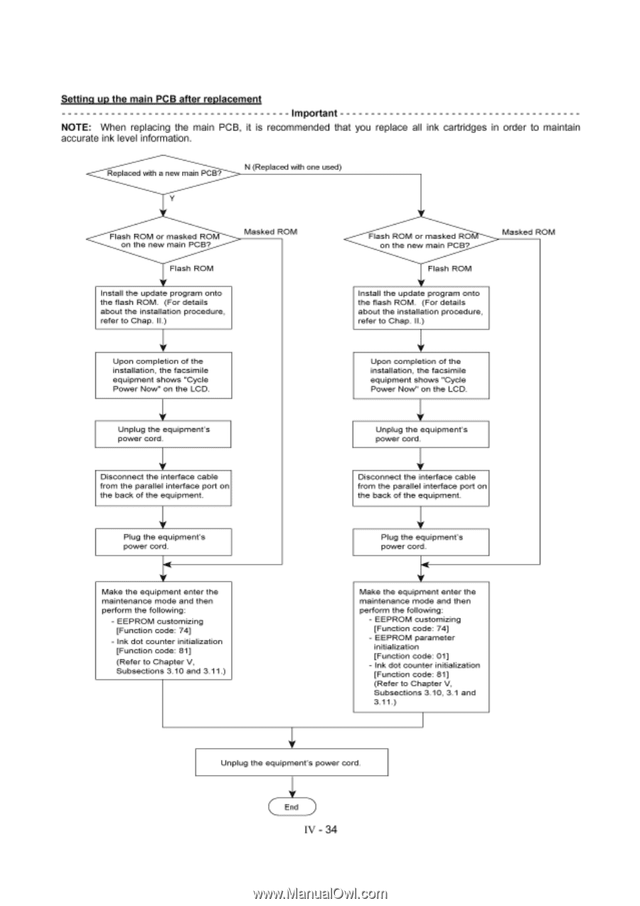
Setting up the main PCB after replacement Important NOTE: When replacing the main PCB, it is recommended that you replace all ink cartridges in order to maintain accurate ink level information. Replaced with a new main PCB? N (Replaced with one used) Flash ROM or masked ROM on the new main PCB? Masked ROM Flash ROM Install the update program onto the flash ROM. (For details about the installation procedure, refer to Chap. II.) Upon completion of the installation, the facsimile equipment shows "Cycle Power Now" on the LCD. Unplug the equipment's power cord. V Disconnect the interface cable from the parallel interface port on the back of the equipment. V Plug the equipment's power cord. Make the equipment enter the maintenance mode and then perform the following: - EEPROM customizing [Function code: 74] - Ink dot counter initialization [Function code: 81] (Refer to Chapter V, Subsections 3.10 and 3.11.) Flash ROM or masked RO on the new main PCB? Masked ROM Flash ROM V Install the update program onto the flash ROM. (For details about the installation procedure, refer to Chap. II.) Upon completion of the installation, the facsimile equipment shows "Cycle Power Now" on the LCD. V Unplug the equipment's power cord. V Disconnect the interface cable from the parallel interface port on the back of the equipment. Plug the equipment's power cord. V Make the equipment enter the maintenance mode and then perform the following: - EEPROM customizing [Function code: 74] - EEPROM parameter initialization [Function code: 01] - Ink dot counter initialization [Function code: 81] (Refer to Chapter V, Subsections 3.10, 3.1 and 3.11.) Unplug the equipment's power cord. End IV - 34
-
 1
1 -
2
-
3
-
4
-
5
-
6
-
7
-
8
-
9
-
10
-
11
-
12
-
13
-
14
-
15
-
16
-
17
-
18
-
19
-
20
-
21
-
22
-
23
-
24
-
25
-
26
-
27
-
28
-
29
-
30
-
31
-
32
-
33
-
34
-
35
-
36
-
37
-
38
-
39
-
40
-
41
-
42
-
43
-
44
-
45
-
46
-
47
-
48
-
49
-
50
-
51
-
52
-
53
-
54
-
55
-
56
-
57
-
58
-
59
-
60
-
 61
61 -
 62
62 -
 63
63 -
 64
64 -
 65
65 -
 66
66 -
 67
67 -
 68
68 -
 69
69 -
 70
70 -
 71
71 -
72
-
73
-
74
-
75
-
76
-
77
-
78
-
79
-
80
-
81
-
82
-
83
-
84
-
85
-
86
-
87
-
88
-
89
-
90
-
91
-
92
-
93
-
94
-
95
-
96
-
97
-
98
-
99
-
100
-
101
-
102
-
103
-
104
-
105
-
106
-
107
-
108
-
109
-
110
-
111
-
112
-
113
-
114
-
115
-
116
-
117
-
118
-
119
-
120
-
121
-
122
-
123
-
124
-
125
-
126
-
127
-
128
-
129
-
130
-
131
-
132
-
133
-
134
-
135
-
136
-
137
-
138
-
139
-
140
-
141
-
142
-
143
 |
 |