Brother International MFC-7050C Service Manual - Page 107
Modem, setting, Selectors, Cable, equalizer, Reception, level, through, Modem, attenuator
 |
View all Brother International MFC-7050C manuals
Add to My Manuals
Save this manual to your list of manuals |
Page 107 highlights
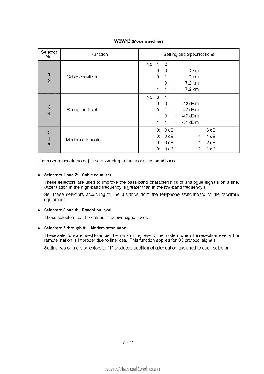
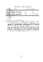
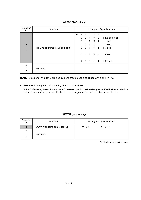
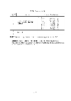
Selector No. 1 2 3 4 5 8 WSW13 (Modem setting) Function Cable equalizer Reception level Modem attenuator Setting and Specifications No. 1 2 00 : 01 : 10 : 11 : No. 3 4 00 : 01 : 10 : 11 : 0: 0dB 0: 0 dB 0: 0 dB 0: 0 dB 0 km 0 km 7.2 km 7.2 km -43 dBm -47 dBm -49 dBm -51 dBm 1: 8 dB 1: 4 dB 1: 2 dB 1: 1 dB The modem should be adjusted according to the user's line conditions. • Selectors 1 and 2: Cable equalizer These selectors are used to improve the pass-band characteristics of analogue signals on a line. (Attenuation in the high-band frequency is greater than in the low-band frequency.) Set these selectors according to the distance from the telephone switchboard to the facsimile equipment. • Selectors 3 and 4: Reception level These selectors set the optimum receive signal level. • Selectors 5 through 8: Modem attenuator These selectors are used to adjust the transmitting level of the modem when the reception level at the remote station is improper due to line loss. This function applies for G3 protocol signals. Setting two or more selectors to "1" produces addition of attenuation assigned to each selector. V - 11
-
 1
1 -
2
-
3
-
4
-
5
-
6
-
7
-
8
-
9
-
10
-
11
-
12
-
13
-
14
-
15
-
16
-
17
-
18
-
19
-
20
-
21
-
22
-
23
-
24
-
25
-
26
-
27
-
28
-
29
-
30
-
31
-
32
-
33
-
34
-
35
-
36
-
37
-
38
-
39
-
40
-
41
-
42
-
43
-
44
-
45
-
46
-
47
-
48
-
49
-
50
-
51
-
52
-
53
-
54
-
55
-
56
-
57
-
58
-
59
-
60
-
61
-
62
-
63
-
64
-
65
-
66
-
67
-
68
-
69
-
70
-
71
-
72
-
73
-
74
-
75
-
76
-
77
-
78
-
79
-
80
-
81
-
82
-
83
-
84
-
85
-
86
-
87
-
88
-
89
-
90
-
91
-
92
-
93
-
94
-
95
-
96
-
97
-
98
-
99
-
100
-
101
-
 102
102 -
 103
103 -
 104
104 -
 105
105 -
 106
106 -
 107
107 -
 108
108 -
 109
109 -
 110
110 -
 111
111 -
 112
112 -
113
-
114
-
115
-
116
-
117
-
118
-
119
-
120
-
121
-
122
-
123
-
124
-
125
-
126
-
127
-
128
-
129
-
130
-
131
-
132
-
133
-
134
-
135
-
136
-
137
-
138
-
139
-
140
-
141
-
142
-
143
 |
 |