Brother International MFC-7050C Service Manual - Page 68
Empty, Sensor, adhesive, attaches, the ink, empty, sensor, harness, frame, chassis, right, side.,
 |
View all Brother International MFC-7050C manuals
Add to My Manuals
Save this manual to your list of manuals |
Page 68 highlights
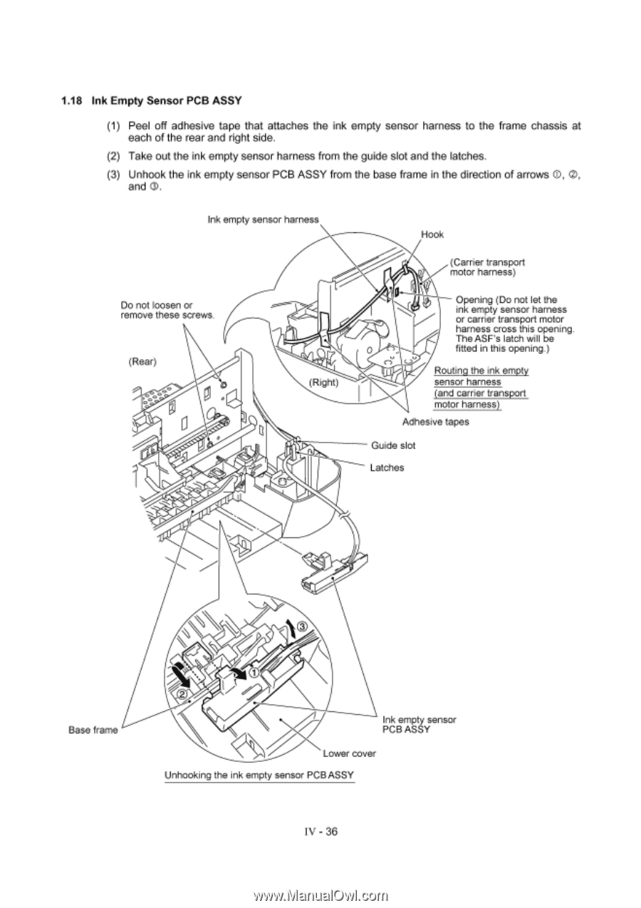
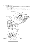
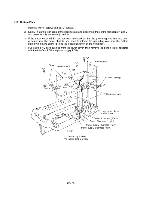
1.18 Ink Empty Sensor PCB ASSY (1) Peel off adhesive tape that attaches the ink empty sensor harness to the frame chassis at each of the rear and right side. (2) Take out the ink empty sensor harness from the guide slot and the latches. (3) Unhook the ink empty sensor PCB ASSY from the base frame in the direction of arrows 0, 0, and O. Ink empty sensor harness Do not loosen or remove these screws. (Rear) 0 (Right) Hook (Carrier transport motor harness) 0 C) Opening (Do not let the ink empty sensor harness or carrier transport motor harness cross this opening. The ASF's latch will be fitted in this opening.) Routing the ink empty sensor harness (and carrier transport motor harness) Adhesive tapes Guide slot Latches Base frame Ink empty sensor PCB ASSY Lower cover Unhooking the ink empty sensor PCB ASSY IV - 36
-
 1
1 -
2
-
3
-
4
-
5
-
6
-
7
-
8
-
9
-
10
-
11
-
12
-
13
-
14
-
15
-
16
-
17
-
18
-
19
-
20
-
21
-
22
-
23
-
24
-
25
-
26
-
27
-
28
-
29
-
30
-
31
-
32
-
33
-
34
-
35
-
36
-
37
-
38
-
39
-
40
-
41
-
42
-
43
-
44
-
45
-
46
-
47
-
48
-
49
-
50
-
51
-
52
-
53
-
54
-
55
-
56
-
57
-
58
-
59
-
60
-
61
-
62
-
 63
63 -
 64
64 -
 65
65 -
 66
66 -
 67
67 -
 68
68 -
 69
69 -
 70
70 -
 71
71 -
 72
72 -
 73
73 -
74
-
75
-
76
-
77
-
78
-
79
-
80
-
81
-
82
-
83
-
84
-
85
-
86
-
87
-
88
-
89
-
90
-
91
-
92
-
93
-
94
-
95
-
96
-
97
-
98
-
99
-
100
-
101
-
102
-
103
-
104
-
105
-
106
-
107
-
108
-
109
-
110
-
111
-
112
-
113
-
114
-
115
-
116
-
117
-
118
-
119
-
120
-
121
-
122
-
123
-
124
-
125
-
126
-
127
-
128
-
129
-
130
-
131
-
132
-
133
-
134
-
135
-
136
-
137
-
138
-
139
-
140
-
141
-
142
-
143
 |
 |