Brother International MFC-7050C Service Manual - Page 80
Maintenance, frame, chassis, unhook, latches, maintenance, ASSY., glued, chassis, points, remove,
 |
View all Brother International MFC-7050C manuals
Add to My Manuals
Save this manual to your list of manuals |
Page 80 highlights
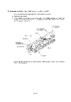
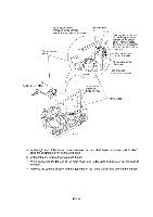
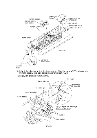
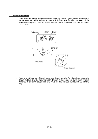
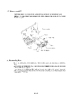
1.26 Maintenance ASSY (1) On the rear side of the frame chassis, unhook the two latches of the maintenance ASSY. NOTE: The maintenance ASSY is glued to the frame chassis at four points, so you need to remove the glue. Frame chassis Cutout 0 Gripper ring Cutout Boss Latches Boss Maintenance ASSY Wiper release lever ■ Reassembling Notes • First fit the two bosses of the maintenance ASSY into the cutouts and then snap the ASSY into place. • When setting the maintenance ASSY back into place or replacing it with a new one, no gluing to the frame chassis is required. If you replace the maintenance ASSY with a new one, you need to set a gripper ring to the shaft of the wiper release lever so that the front-to-rear looseness of the wiper release lever comes to 0.5 +0.3/-0 mm. IV - 48
-
 1
1 -
2
-
3
-
4
-
5
-
6
-
7
-
8
-
9
-
10
-
11
-
12
-
13
-
14
-
15
-
16
-
17
-
18
-
19
-
20
-
21
-
22
-
23
-
24
-
25
-
26
-
27
-
28
-
29
-
30
-
31
-
32
-
33
-
34
-
35
-
36
-
37
-
38
-
39
-
40
-
41
-
42
-
43
-
44
-
45
-
46
-
47
-
48
-
49
-
50
-
51
-
52
-
53
-
54
-
55
-
56
-
57
-
58
-
59
-
60
-
61
-
62
-
63
-
64
-
65
-
66
-
67
-
68
-
69
-
70
-
71
-
72
-
73
-
74
-
 75
75 -
 76
76 -
 77
77 -
 78
78 -
 79
79 -
 80
80 -
 81
81 -
 82
82 -
 83
83 -
 84
84 -
 85
85 -
86
-
87
-
88
-
89
-
90
-
91
-
92
-
93
-
94
-
95
-
96
-
97
-
98
-
99
-
100
-
101
-
102
-
103
-
104
-
105
-
106
-
107
-
108
-
109
-
110
-
111
-
112
-
113
-
114
-
115
-
116
-
117
-
118
-
119
-
120
-
121
-
122
-
123
-
124
-
125
-
126
-
127
-
128
-
129
-
130
-
131
-
132
-
133
-
134
-
135
-
136
-
137
-
138
-
139
-
140
-
141
-
142
-
143
 |
 |
