Brother International MFC-7050C Service Manual - Page 65
connecting
 |
View all Brother International MFC-7050C manuals
Add to My Manuals
Save this manual to your list of manuals |
Page 65 highlights
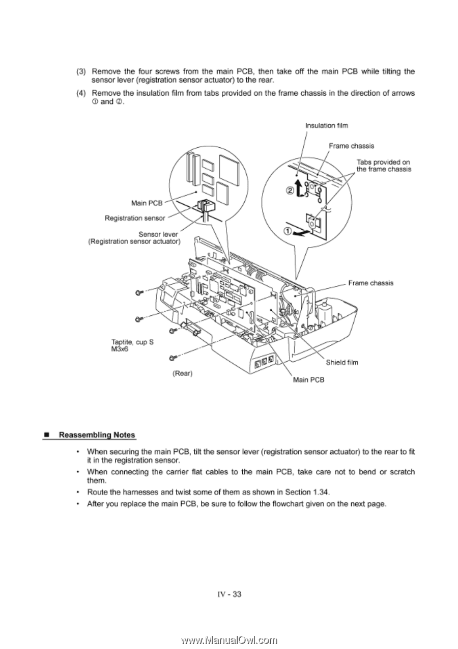
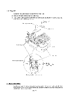
(3) Remove the four screws from the main PCB, then take off the main PCB while tilting the sensor lever (registration sensor actuator) to the rear. (4) Remove the insulation film from tabs provided on the frame chassis in the direction of arrows O and O. Main PCB Registration sensor Sensor lever (Registration sensor actuator) Insulation film Frame chassis Tabs provided on the frame chassis 0 Taptite, cup S M3x6 Cr(Rear) LJ N Frame chassis Shield film Main PCB ■ Reassembling Notes • When securing the main PCB, tilt the sensor lever (registration sensor actuator) to the rear to fit it in the registration sensor. • When connecting the carrier flat cables to the main PCB, take care not to bend or scratch them. • Route the harnesses and twist some of them as shown in Section 1.34. • After you replace the main PCB, be sure to follow the flowchart given on the next page. IV - 33
-
 1
1 -
2
-
3
-
4
-
5
-
6
-
7
-
8
-
9
-
10
-
11
-
12
-
13
-
14
-
15
-
16
-
17
-
18
-
19
-
20
-
21
-
22
-
23
-
24
-
25
-
26
-
27
-
28
-
29
-
30
-
31
-
32
-
33
-
34
-
35
-
36
-
37
-
38
-
39
-
40
-
41
-
42
-
43
-
44
-
45
-
46
-
47
-
48
-
49
-
50
-
51
-
52
-
53
-
54
-
55
-
56
-
57
-
58
-
59
-
 60
60 -
 61
61 -
 62
62 -
 63
63 -
 64
64 -
 65
65 -
 66
66 -
 67
67 -
 68
68 -
 69
69 -
 70
70 -
71
-
72
-
73
-
74
-
75
-
76
-
77
-
78
-
79
-
80
-
81
-
82
-
83
-
84
-
85
-
86
-
87
-
88
-
89
-
90
-
91
-
92
-
93
-
94
-
95
-
96
-
97
-
98
-
99
-
100
-
101
-
102
-
103
-
104
-
105
-
106
-
107
-
108
-
109
-
110
-
111
-
112
-
113
-
114
-
115
-
116
-
117
-
118
-
119
-
120
-
121
-
122
-
123
-
124
-
125
-
126
-
127
-
128
-
129
-
130
-
131
-
132
-
133
-
134
-
135
-
136
-
137
-
138
-
139
-
140
-
141
-
142
-
143
 |
 |