Brother International MFC-7050C Service Manual - Page 70
Brother International MFC-7050C Manual
 |
View all Brother International MFC-7050C manuals
Add to My Manuals
Save this manual to your list of manuals |
Page 70 highlights
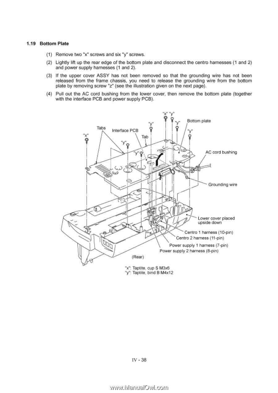
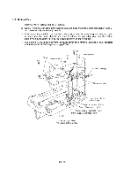
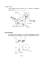
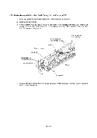
1.19 Bottom Plate (1) Remove two "x" screws and six "y" screws. (2) Lightly lift up the rear edge of the bottom plate and disconnect the centro harnesses (1 and 2) and power supply harnesses (1 and 2). (3) If the upper cover ASSY has not been removed so that the grounding wire has not been released from the frame chassis, you need to release the grounding wire from the bottom plate by removing screw "z" (see the illustration given on the next page). (4) Pull out the AC cord bushing from the lower cover, then remove the bottom plate (together with the interface PCB and power supply PCB). Tabs Interface PCB ry: Tab ? „ „ Bottom plate 'y AC cord bushing C.) 0 Grounding wire (Rear) Lower cover placed upside down Centro 1 harness (10-pin) Centro 2 harness (11-pin) Power supply 1 harness (7-pin) Power supply 2 harness (8-pin) "x": Taptite, cup S M3x6 "y": Taptite, bind B M4x12 IV - 38
-
 1
1 -
2
-
3
-
4
-
5
-
6
-
7
-
8
-
9
-
10
-
11
-
12
-
13
-
14
-
15
-
16
-
17
-
18
-
19
-
20
-
21
-
22
-
23
-
24
-
25
-
26
-
27
-
28
-
29
-
30
-
31
-
32
-
33
-
34
-
35
-
36
-
37
-
38
-
39
-
40
-
41
-
42
-
43
-
44
-
45
-
46
-
47
-
48
-
49
-
50
-
51
-
52
-
53
-
54
-
55
-
56
-
57
-
58
-
59
-
60
-
61
-
62
-
63
-
64
-
 65
65 -
 66
66 -
 67
67 -
 68
68 -
 69
69 -
 70
70 -
 71
71 -
 72
72 -
 73
73 -
 74
74 -
 75
75 -
76
-
77
-
78
-
79
-
80
-
81
-
82
-
83
-
84
-
85
-
86
-
87
-
88
-
89
-
90
-
91
-
92
-
93
-
94
-
95
-
96
-
97
-
98
-
99
-
100
-
101
-
102
-
103
-
104
-
105
-
106
-
107
-
108
-
109
-
110
-
111
-
112
-
113
-
114
-
115
-
116
-
117
-
118
-
119
-
120
-
121
-
122
-
123
-
124
-
125
-
126
-
127
-
128
-
129
-
130
-
131
-
132
-
133
-
134
-
135
-
136
-
137
-
138
-
139
-
140
-
141
-
142
-
143
 |
 |