Brother International MFC-7050C Service Manual - Page 67
Video, Disconnect, video, capture, harness, Remove, screw, three, guides., connected, rear.
 |
View all Brother International MFC-7050C manuals
Add to My Manuals
Save this manual to your list of manuals |
Page 67 highlights
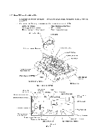
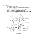
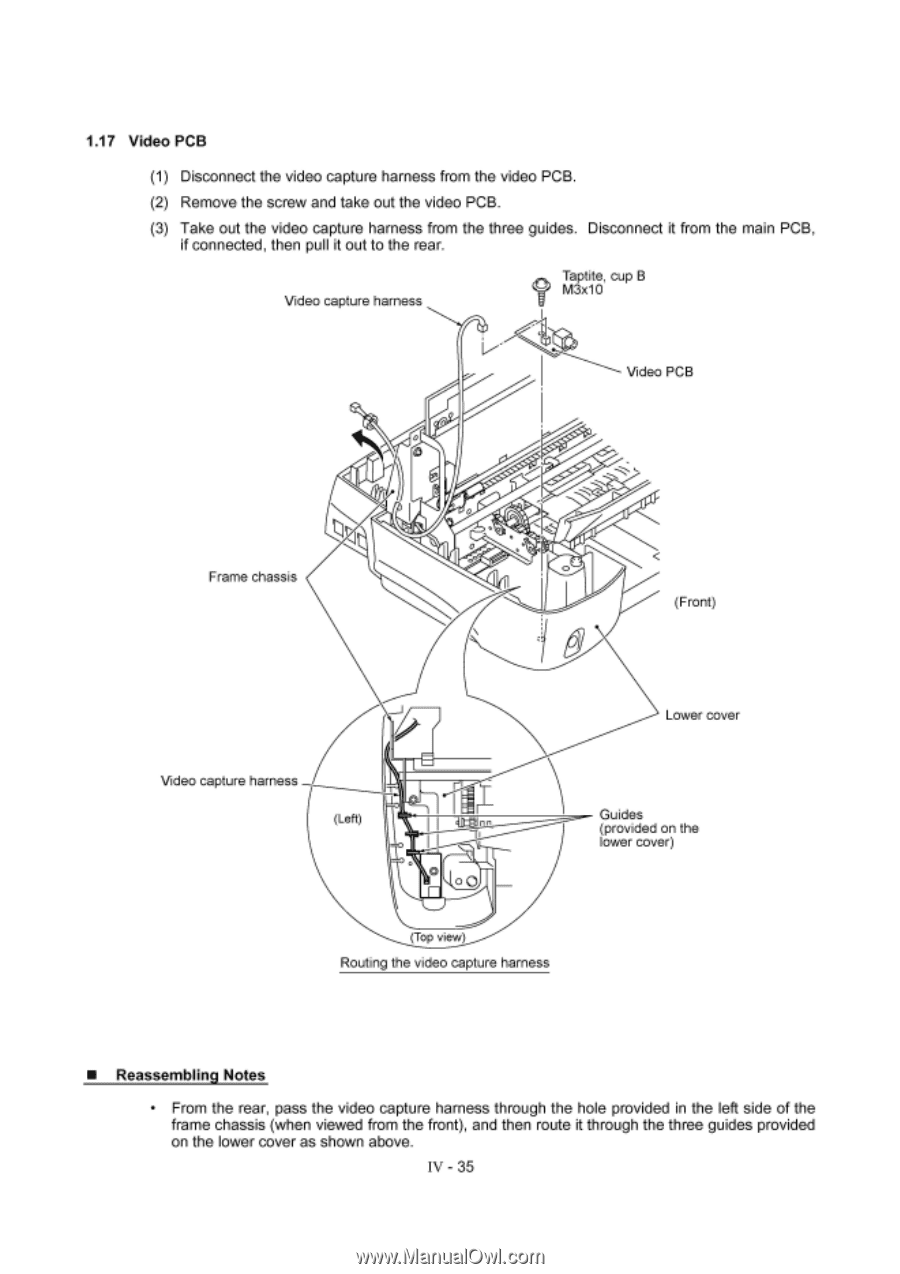
1.17 Video PCB (1) Disconnect the video capture harness from the video PCB. (2) Remove the screw and take out the video PCB. (3) Take out the video capture harness from the three guides. Disconnect it from the main PCB, if connected, then pull it out to the rear. Video capture harness Taptite, cup B M3x10 Video PCB Frame chassis 0 0 (Front) Video capture harness (Left) Lower cover Guides nn (provided on the lower cover) (Top view) Routing the video capture harness ■ Reassembling Notes • From the rear, pass the video capture harness through the hole provided in the left side of the frame chassis (when viewed from the front), and then route it through the three guides provided on the lower cover as shown above. IV - 35
-
 1
1 -
2
-
3
-
4
-
5
-
6
-
7
-
8
-
9
-
10
-
11
-
12
-
13
-
14
-
15
-
16
-
17
-
18
-
19
-
20
-
21
-
22
-
23
-
24
-
25
-
26
-
27
-
28
-
29
-
30
-
31
-
32
-
33
-
34
-
35
-
36
-
37
-
38
-
39
-
40
-
41
-
42
-
43
-
44
-
45
-
46
-
47
-
48
-
49
-
50
-
51
-
52
-
53
-
54
-
55
-
56
-
57
-
58
-
59
-
60
-
61
-
 62
62 -
 63
63 -
 64
64 -
 65
65 -
 66
66 -
 67
67 -
 68
68 -
 69
69 -
 70
70 -
 71
71 -
 72
72 -
73
-
74
-
75
-
76
-
77
-
78
-
79
-
80
-
81
-
82
-
83
-
84
-
85
-
86
-
87
-
88
-
89
-
90
-
91
-
92
-
93
-
94
-
95
-
96
-
97
-
98
-
99
-
100
-
101
-
102
-
103
-
104
-
105
-
106
-
107
-
108
-
109
-
110
-
111
-
112
-
113
-
114
-
115
-
116
-
117
-
118
-
119
-
120
-
121
-
122
-
123
-
124
-
125
-
126
-
127
-
128
-
129
-
130
-
131
-
132
-
133
-
134
-
135
-
136
-
137
-
138
-
139
-
140
-
141
-
142
-
143
 |
 |
1.17
Video
PCB
(1)
Disconnect
the
video
capture
harness
from
the
video
PCB.
(2)
Remove
the
screw
and
take
out
the
video
PCB.
(3)
Take
out
the
video
capture
harness
from
the
three
guides.
Disconnect
it
from
the
main
PCB,
if
connected,
then
pull
it
out
to
the
rear.
Video
capture
harness
Frame
chassis
Video
capture
harness
(Left)
0
Taptite,
cup
B
M3x1
0
Video
PCB
0
nn
(Top
view)
Routing
the
video
capture
harness
■
Reassembling
Notes
(Front)
Lower
cover
Guides
(provided
on
the
lower
cover)
•
From
the
rear,
pass
the
video
capture
harness
through
the
hole
provided
in
the
left
side
of
the
frame
chassis
(when
viewed
from
the
front),
and
then
route
it
through
the
three
guides
provided
on
the
lower
cover
as
shown
above.
IV
-
35