Dell PowerConnect 3524 User's Guide - Page 35
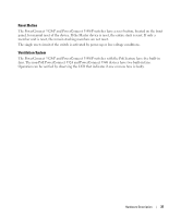
Power Supplies, Backup Master.
 |
View all Dell PowerConnect 3524 manuals
Add to My Manuals
Save this manual to your list of manuals |
Page 35 highlights
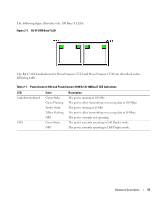
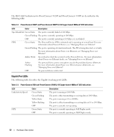
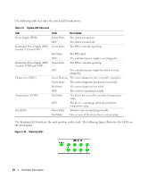
The Stacking LEDs are numbered 1- 8. Each stacking unit has one stacking LED lit, indicating its Unit ID number. If either Stacking LED 1 or 2 is lit, it indicates that the device is either the Stack Master or Backup Master. Table 2-6. Stacking LED Indications LED Color All Stacking LEDs OFF Stacking LED 1-8 (S1-S8) Green Static OFF Stacking Master LED Green Static OFF Description The switch is currently a stand-alone device. The device is designated as Stacking Unit N. The device is not designated as Stacking Unit N. The device is the Stack Master The device is not the Stack Master. Power Supplies The device has an internal power supply unit (AC unit) and a connector to connect PowerConnect 3524/P and PowerConnect 3548/P devices to a PowerConnect EPS-470 unit, or to connect PowerConnect 3524 and PowerConnect 3548 devices to a PowerConnect RPS-600 unit. The PowerConnect 3524/P and PowerConnect 3548/P devices have an internal power supply (12 Volt). Operation with both power supply units is regulated through load sharing. Power supply LEDs indicate the status of the power supply. The PowerConnect 3524/P and PowerConnect 3548/P devices have an internal power supply of 470W (12V/-48V), with a total of 370W for 24 ports PoE device. AC Power Supply Unit The AC power supply unit operates from 90 to 264 VAC, 47 to 63 Hz. The AC power supply unit uses a standard connector. LED indicator is on the front panel and indicates whether the AC unit is connected. DC Power Supply Unit The PowerConnect 3524 and PowerConnect 3548 switches connect to an external RPS-600 unit to provide a redundant power option. No configuration is required. The front panel "RPS" LED indicates whether the external RPS-600 is connected. See Table 2-5 for RPS LED definition. The PowerConnect 3524/P and PowerConnect 3548/P switches connect to an external EPS-470 unit to provide a redundant power option. No configuration is required. The front panel "RPS" LED indicates whether the external EPS-470 is connected. See Table 2-5 for RPS LED definition. Hardware Description 35
-
 1
1 -
2
-
3
-
4
-
5
-
6
-
7
-
8
-
9
-
10
-
11
-
12
-
13
-
14
-
15
-
16
-
17
-
18
-
19
-
20
-
21
-
22
-
23
-
24
-
25
-
26
-
27
-
28
-
29
-
 30
30 -
 31
31 -
 32
32 -
 33
33 -
 34
34 -
 35
35 -
 36
36 -
 37
37 -
 38
38 -
 39
39 -
 40
40 -
41
-
42
-
43
-
44
-
45
-
46
-
47
-
48
-
49
-
50
-
51
-
52
-
53
-
54
-
55
-
56
-
57
-
58
-
59
-
60
-
61
-
62
-
63
-
64
-
65
-
66
-
67
-
68
-
69
-
70
-
71
-
72
-
73
-
74
-
75
-
76
-
77
-
78
-
79
-
80
-
81
-
82
-
83
-
84
-
85
-
86
-
87
-
88
-
89
-
90
-
91
-
92
-
93
-
94
-
95
-
96
-
97
-
98
-
99
-
100
-
101
-
102
-
103
-
104
-
105
-
106
-
107
-
108
-
109
-
110
-
111
-
112
-
113
-
114
-
115
-
116
-
117
-
118
-
119
-
120
-
121
-
122
-
123
-
124
-
125
-
126
-
127
-
128
-
129
-
130
-
131
-
132
-
133
-
134
-
135
-
136
-
137
-
138
-
139
-
140
-
141
-
142
-
143
-
144
-
145
-
146
-
147
-
148
-
149
-
150
-
151
-
152
-
153
-
154
-
155
-
156
-
157
-
158
-
159
-
160
-
161
-
162
-
163
-
164
-
165
-
166
-
167
-
168
-
169
-
170
-
171
-
172
-
173
-
174
-
175
-
176
-
177
-
178
-
179
-
180
-
181
-
182
-
183
-
184
-
185
-
186
-
187
-
188
-
189
-
190
-
191
-
192
-
193
-
194
-
195
-
196
-
197
-
198
-
199
-
200
-
201
-
202
-
203
-
204
-
205
-
206
-
207
-
208
-
209
-
210
-
211
-
212
-
213
-
214
-
215
-
216
-
217
-
218
-
219
-
220
-
221
-
222
-
223
-
224
-
225
-
226
-
227
-
228
-
229
-
230
-
231
-
232
-
233
-
234
-
235
-
236
-
237
-
238
-
239
-
240
-
241
-
242
-
243
-
244
-
245
-
246
-
247
-
248
-
249
-
250
-
251
-
252
-
253
-
254
-
255
-
256
-
257
-
258
-
259
-
260
-
261
-
262
-
263
-
264
-
265
-
266
-
267
-
268
-
269
-
270
-
271
-
272
-
273
-
274
-
275
-
276
-
277
-
278
-
279
-
280
-
281
-
282
-
283
-
284
-
285
-
286
-
287
-
288
-
289
-
290
-
291
-
292
-
293
-
294
-
295
-
296
-
297
-
298
-
299
-
300
-
301
-
302
-
303
-
304
-
305
-
306
-
307
-
308
-
309
-
310
-
311
-
312
-
313
-
314
-
315
-
316
-
317
-
318
-
319
-
320
-
321
-
322
-
323
-
324
-
325
-
326
-
327
-
328
-
329
-
330
-
331
-
332
-
333
-
334
-
335
-
336
-
337
-
338
-
339
-
340
-
341
-
342
-
343
-
344
-
345
-
346
-
347
-
348
-
349
-
350
-
351
-
352
-
353
-
354
-
355
-
356
-
357
-
358
-
359
-
360
-
361
-
362
-
363
-
364
-
365
-
366
-
367
-
368
-
369
-
370
-
371
-
372
-
373
-
374
-
375
-
376
-
377
-
378
-
379
-
380
-
381
-
382
-
383
-
384
-
385
-
386
-
387
-
388
-
389
-
390
-
391
-
392
-
393
-
394
-
395
-
396
-
397
-
398
-
399
-
400
-
401
-
402
-
403
-
404
-
405
-
406
-
407
-
408
-
409
-
410
-
411
-
412
-
413
-
414
-
415
-
416
-
417
-
418
-
419
-
420
-
421
-
422
-
423
-
424
-
425
-
426
-
427
-
428
-
429
-
430
-
431
-
432
-
433
-
434
-
435
-
436
-
437
-
438
-
439
-
440
-
441
-
442
-
443
-
444
-
445
-
446
-
447
-
448
-
449
-
450
-
451
-
452
-
453
-
454
-
455
-
456
-
457
-
458
-
459
-
460
-
461
-
462
-
463
-
464
-
465
-
466
-
467
-
468
-
469
-
470
-
471
-
472
-
473
-
474
 |
 |
