HP 4300 Service Manual - Page 95
Overcurrent/overvoltage protection, Toner detection, Cartridge detection, Cartridge memory - cartridge error
 |
UPC - 808736312264
View all HP 4300 manuals
Add to My Manuals
Save this manual to your list of manuals |
Page 95 highlights
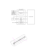
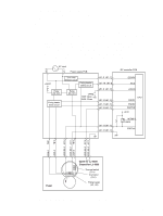
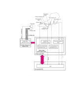
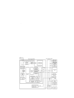
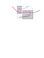
Overcurrent/overvoltage protection If a short-circuit or other problem on the load side causes an excessive current flow or generates abnormal voltage, the overcurrent/overvoltage protection systems automatically cut off the output voltage to protect the power supply circuit. If the overcurrent or overvoltage protection system are activated and the power supply circuit does not generate dc voltage, it is necessary to turn the power off, correct the problem, and then turn the printer on again. The circuit has two fuses (FU1, FU2), which break and cut off the output voltage if overcurrent flows through the ac line. Toner detection To monitor the toner level, the printer uses two plate antennas and a toner level circuit in the high-voltage power supply circuit (see figure 10 on page 73). Toner level detection is performed by the DC controller PCA which monitors the output signal of this circuit. The signal is fed back to the DC controller PCA from the antennas during the wait and standby operating periods (see table 30 on page 67). The DC controller PCA detects toner level from 1 percent to 100 percent. If the toner is detected as being low, a message will appear on the control-panel display (see "Alphabetical printer messages" on page 258). Cartridge detection The presence of the cartridge is detected using information stored in plate antenna 2 and the print cartridge memory tag (see "High-voltage circuit block diagram" on page 73). The DC controller PCA detects the presence (or lack of) the print cartridge during the wait operating sequence ((see table 30 on page 67). Cartridge memory This memory is built-in EEPROM in the cartridge, so that the printer is capable of detecting the cartridge conditions. Read/write of the cartridge memory is performed by the memory controller board through the antenna unit. The cartridge information read by the memory controller is updated by the DC controller PCA and written to the memory. The read/write of the memory is implemented when the memory controller board receives a command from the DC controller PCA. The DC controller PCA instructs the memory controller to perform read/write at the following timing. Reading timing q When the power is turned on q When the door is closed q When the DC controller PCA receives a command from the formatter Writing timing q When printing is completed q When the DC controller PCA receives a command from the formatter The memory data sent from the memory controller also contains the error status that has occurred during read/write operation. When error status is sent, the DC controller PCA attempts to read the operation four times. If the error status is not cleared after the operation, the DC controller PCA determines one of the following error conditions: sub-CPU failure, memory data abnormality, or memory access abnormality. Do not remove the toner cartridge when the top cover interlock is overridden. Cartridge memory will be disabled. Q2431-90912 Chapter 5 Theory of operation 75
-
 1
1 -
2
-
3
-
4
-
5
-
6
-
7
-
8
-
9
-
10
-
11
-
12
-
13
-
14
-
15
-
16
-
17
-
18
-
19
-
20
-
21
-
22
-
23
-
24
-
25
-
26
-
27
-
28
-
29
-
30
-
31
-
32
-
33
-
34
-
35
-
36
-
37
-
38
-
39
-
40
-
41
-
42
-
43
-
44
-
45
-
46
-
47
-
48
-
49
-
50
-
51
-
52
-
53
-
54
-
55
-
56
-
57
-
58
-
59
-
60
-
61
-
62
-
63
-
64
-
65
-
66
-
67
-
68
-
69
-
70
-
71
-
72
-
73
-
74
-
75
-
76
-
77
-
78
-
79
-
80
-
81
-
82
-
83
-
84
-
85
-
86
-
87
-
88
-
89
-
 90
90 -
 91
91 -
 92
92 -
 93
93 -
 94
94 -
 95
95 -
 96
96 -
 97
97 -
 98
98 -
 99
99 -
 100
100 -
101
-
102
-
103
-
104
-
105
-
106
-
107
-
108
-
109
-
110
-
111
-
112
-
113
-
114
-
115
-
116
-
117
-
118
-
119
-
120
-
121
-
122
-
123
-
124
-
125
-
126
-
127
-
128
-
129
-
130
-
131
-
132
-
133
-
134
-
135
-
136
-
137
-
138
-
139
-
140
-
141
-
142
-
143
-
144
-
145
-
146
-
147
-
148
-
149
-
150
-
151
-
152
-
153
-
154
-
155
-
156
-
157
-
158
-
159
-
160
-
161
-
162
-
163
-
164
-
165
-
166
-
167
-
168
-
169
-
170
-
171
-
172
-
173
-
174
-
175
-
176
-
177
-
178
-
179
-
180
-
181
-
182
-
183
-
184
-
185
-
186
-
187
-
188
-
189
-
190
-
191
-
192
-
193
-
194
-
195
-
196
-
197
-
198
-
199
-
200
-
201
-
202
-
203
-
204
-
205
-
206
-
207
-
208
-
209
-
210
-
211
-
212
-
213
-
214
-
215
-
216
-
217
-
218
-
219
-
220
-
221
-
222
-
223
-
224
-
225
-
226
-
227
-
228
-
229
-
230
-
231
-
232
-
233
-
234
-
235
-
236
-
237
-
238
-
239
-
240
-
241
-
242
-
243
-
244
-
245
-
246
-
247
-
248
-
249
-
250
-
251
-
252
-
253
-
254
-
255
-
256
-
257
-
258
-
259
-
260
-
261
-
262
-
263
-
264
-
265
-
266
-
267
-
268
-
269
-
270
-
271
-
272
-
273
-
274
-
275
-
276
-
277
-
278
-
279
-
280
-
281
-
282
-
283
-
284
-
285
-
286
-
287
-
288
-
289
-
290
-
291
-
292
-
293
-
294
-
295
-
296
-
297
-
298
-
299
-
300
-
301
-
302
-
303
-
304
-
305
-
306
-
307
-
308
-
309
-
310
-
311
-
312
-
313
-
314
-
315
-
316
-
317
-
318
-
319
-
320
-
321
-
322
-
323
-
324
-
325
-
326
-
327
-
328
-
329
-
330
-
331
-
332
-
333
-
334
-
335
-
336
-
337
-
338
-
339
-
340
-
341
-
342
-
343
-
344
-
345
-
346
-
347
-
348
-
349
-
350
-
351
-
352
-
353
-
354
-
355
-
356
-
357
-
358
-
359
-
360
-
361
-
362
-
363
-
364
-
365
-
366
-
367
-
368
-
369
-
370
-
371
-
372
-
373
-
374
-
375
-
376
-
377
-
378
-
379
-
380
-
381
-
382
-
383
-
384
-
385
-
386
-
387
-
388
-
389
-
390
-
391
-
392
-
393
-
394
-
395
-
396
-
397
-
398
-
399
-
400
-
401
-
402
-
403
-
404
-
405
-
406
-
407
-
408
-
409
-
410
-
411
-
412
-
413
-
414
-
415
-
416
-
417
-
418
-
419
-
420
-
421
-
422
-
423
-
424
-
425
-
426
-
427
-
428
-
429
-
430
-
431
-
432
-
433
-
434
-
435
-
436
-
437
-
438
-
439
-
440
-
441
-
442
-
443
-
444
-
445
-
446
-
447
-
448
-
449
-
450
-
451
-
452
 |
 |