HP LaserJet M1005 Service Manual - Page 107
Power supply, Reinstallation tip,
 |
View all HP LaserJet M1005 manuals
Add to My Manuals
Save this manual to your list of manuals |
Page 107 highlights
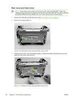
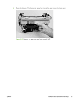
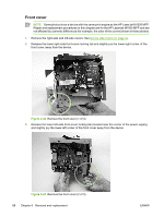
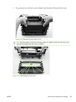
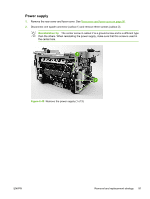
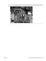
Power supply 1. Remove the rear cover and fuser cover. See Rear cover and fuser cover on page 86. 2. Disconnect one spade connector (callout 1) and remove three screws (callout 2). Reinstallation tip The center screw in callout 2 is a ground screw and is a different type than the others. When reinstalling the power supply, make sure that this screw is used in the center hole. Figure 6-48 Remove the power supply (1 of 3) ENWW Removal and replacement strategy 91
-
 1
1 -
2
-
3
-
4
-
5
-
6
-
7
-
8
-
9
-
10
-
11
-
12
-
13
-
14
-
15
-
16
-
17
-
18
-
19
-
20
-
21
-
22
-
23
-
24
-
25
-
26
-
27
-
28
-
29
-
30
-
31
-
32
-
33
-
34
-
35
-
36
-
37
-
38
-
39
-
40
-
41
-
42
-
43
-
44
-
45
-
46
-
47
-
48
-
49
-
50
-
51
-
52
-
53
-
54
-
55
-
56
-
57
-
58
-
59
-
60
-
61
-
62
-
63
-
64
-
65
-
66
-
67
-
68
-
69
-
70
-
71
-
72
-
73
-
74
-
75
-
76
-
77
-
78
-
79
-
80
-
81
-
82
-
83
-
84
-
85
-
86
-
87
-
88
-
89
-
90
-
91
-
92
-
93
-
94
-
95
-
96
-
97
-
98
-
99
-
100
-
101
-
 102
102 -
 103
103 -
 104
104 -
 105
105 -
 106
106 -
 107
107 -
 108
108 -
 109
109 -
 110
110 -
 111
111 -
 112
112 -
113
-
114
-
115
-
116
-
117
-
118
-
119
-
120
-
121
-
122
-
123
-
124
-
125
-
126
-
127
-
128
-
129
-
130
-
131
-
132
-
133
-
134
-
135
-
136
-
137
-
138
-
139
-
140
-
141
-
142
-
143
-
144
-
145
-
146
-
147
-
148
-
149
-
150
-
151
-
152
-
153
-
154
-
155
-
156
-
157
-
158
-
159
-
160
-
161
-
162
-
163
-
164
-
165
-
166
-
167
-
168
-
169
-
170
-
171
-
172
-
173
-
174
-
175
-
176
-
177
-
178
-
179
-
180
-
181
-
182
-
183
-
184
-
185
-
186
-
187
-
188
-
189
-
190
-
191
-
192
-
193
-
194
-
195
-
196
-
197
-
198
-
199
-
200
-
201
-
202
-
203
-
204
-
205
-
206
-
207
-
208
-
209
-
210
-
211
-
212
-
213
-
214
-
215
-
216
-
217
-
218
-
219
-
220
-
221
-
222
-
223
-
224
 |
 |
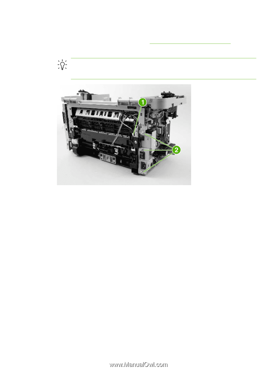
Power supply
1.
Remove the rear cover and fuser cover. See
Rear cover and fuser cover
on page
86
.
2.
Disconnect one spade connector (callout 1) and remove three screws (callout 2).
Reinstallation tip
The center screw in callout 2 is a ground screw and is a different type
than the others. When reinstalling the power supply, make sure that this screw is used in
the center hole.
Figure 6-48
Remove the power supply (1 of 3)
ENWW
Removal and replacement strategy
91