HP LaserJet M1005 Service Manual - Page 7

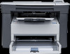
HP LaserJet M1005 MFP unique components, Removal and replacement

Page 7 highlights

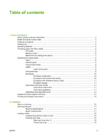
Standard boot process ...46 Device startup messages 46 RAM ...47 Universal serial bus (USB) interface 47 Control panel ...47 EconoMode ...47 Device functions ...48 Engine control system (engine control unit and power-supply assembly 48 Device engine control system 49 Device laser/scanner unit 49 Power system on the power-supply assembly 49 Image-formation system ...51 The seven image-formation processes 52 Print cartridge ...53 Device paper-feed system 53 Jam detection in the device 54 Conditions of jam detection 54 HP LaserJet M1005 MFP unique components 56 Scanner functions and operation 56 Scanner functions 56 Scanner operation 57 6 Removal and replacement Removal and replacement strategy ...60 Admonitions ...60 Required tools ...60 Before performing service 61 After performing service ...61 Parts removal order ...61 Flatbed lid ...63 Control-panel overlay ...64 Control panel ...65 Scanner assembly ...67 Device separation pad ...73 Print cartridge ...74 Device pickup roller ...75 Media input tray ...78 Transfer roller ...80 Device side covers ...82 Print-cartridge door ...85 Rear cover and fuser cover 86 Front cover ...88 Installing the scanner cushions 90 Power supply ...91 Formatter ...94 Scanner support frame ...95 Engine controller unit ...98 Laser/scanner assembly 102 Main motor ...103 Fuser ...105 ENWW v

  • 1
  • 2
  • 3
  • 4
  • 5
  • 6
  • 7
  • 8
  • 9
  • 10
  • 11
  • 12
  • 13
  • 14
  • 15
  • 16
  • 17
  • 18
  • 19
  • 20
  • 21
  • 22
  • 23
  • 24
  • 25
  • 26
  • 27
  • 28
  • 29
  • 30
  • 31
  • 32
  • 33
  • 34
  • 35
  • 36
  • 37
  • 38
  • 39
  • 40
  • 41
  • 42
  • 43
  • 44
  • 45
  • 46
  • 47
  • 48
  • 49
  • 50
  • 51
  • 52
  • 53
  • 54
  • 55
  • 56
  • 57
  • 58
  • 59
  • 60
  • 61
  • 62
  • 63
  • 64
  • 65
  • 66
  • 67
  • 68
  • 69
  • 70
  • 71
  • 72
  • 73
  • 74
  • 75
  • 76
  • 77
  • 78
  • 79
  • 80
  • 81
  • 82
  • 83
  • 84
  • 85
  • 86
  • 87
  • 88
  • 89
  • 90
  • 91
  • 92
  • 93
  • 94
  • 95
  • 96
  • 97
  • 98
  • 99
  • 100
  • 101
  • 102
  • 103
  • 104
  • 105
  • 106
  • 107
  • 108
  • 109
  • 110
  • 111
  • 112
  • 113
  • 114
  • 115
  • 116
  • 117
  • 118
  • 119
  • 120
  • 121
  • 122
  • 123
  • 124
  • 125
  • 126
  • 127
  • 128
  • 129
  • 130
  • 131
  • 132
  • 133
  • 134
  • 135
  • 136
  • 137
  • 138
  • 139
  • 140
  • 141
  • 142
  • 143
  • 144
  • 145
  • 146
  • 147
  • 148
  • 149
  • 150
  • 151
  • 152
  • 153
  • 154
  • 155
  • 156
  • 157
  • 158
  • 159
  • 160
  • 161
  • 162
  • 163
  • 164
  • 165
  • 166
  • 167
  • 168
  • 169
  • 170
  • 171
  • 172
  • 173
  • 174
  • 175
  • 176
  • 177
  • 178
  • 179
  • 180
  • 181
  • 182
  • 183
  • 184
  • 185
  • 186
  • 187
  • 188
  • 189
  • 190
  • 191
  • 192
  • 193
  • 194
  • 195
  • 196
  • 197
  • 198
  • 199
  • 200
  • 201
  • 202
  • 203
  • 204
  • 205
  • 206
  • 207
  • 208
  • 209
  • 210
  • 211
  • 212
  • 213
  • 214
  • 215
  • 216
  • 217
  • 218
  • 219
  • 220
  • 221
  • 222
  • 223
  • 224

Standard boot process
.......................................................................................................
46
Device startup messages
..................................................................................
46
RAM
...................................................................................................................................
47
Universal serial bus (USB) interface
..................................................................................
47
Control panel
.....................................................................................................................
47
EconoMode
........................................................................................................................
47
Device functions
.................................................................................................................................
48
Engine control system (engine control unit and power-supply assembly)
.........................
48
Device engine control system
...........................................................................
49
Device laser/scanner unit
.................................................................................
49
Power system on the power-supply assembly
..................................................
49
Image-formation system
....................................................................................................
51
The seven image-formation processes
............................................................
52
Print cartridge
....................................................................................................................
53
Device paper-feed system
.................................................................................................
53
Jam detection in the device
...............................................................................................
54
Conditions of jam detection
...............................................................................
54
HP LaserJet M1005 MFP unique components
...................................................................................
56
Scanner functions and operation
.......................................................................................
56
Scanner functions
............................................................................................
56
Scanner operation
.............................................................................................
57
6
Removal and replacement
Removal and replacement strategy
....................................................................................................
60
Admonitions
.......................................................................................................................
60
Required tools
....................................................................................................................
60
Before performing service
..................................................................................................
61
After performing service
.....................................................................................................
61
Parts removal order
...........................................................................................................
61
Flatbed lid
..........................................................................................................................
63
Control-panel overlay
.........................................................................................................
64
Control panel
.....................................................................................................................
65
Scanner assembly
.............................................................................................................
67
Device separation pad
.......................................................................................................
73
Print cartridge
....................................................................................................................
74
Device pickup roller
...........................................................................................................
75
Media input tray
.................................................................................................................
78
Transfer roller
....................................................................................................................
80
Device side covers
.............................................................................................................
82
Print-cartridge door
............................................................................................................
85
Rear cover and fuser cover
...............................................................................................
86
Front cover
.........................................................................................................................
88
Installing the scanner cushions
..........................................................................................
90
Power supply
.....................................................................................................................
91
Formatter
...........................................................................................................................
94
Scanner support frame
.....................................................................................................
95
Engine controller unit
.........................................................................................................
98
Laser/scanner assembly
..................................................................................................
102
Main motor
.......................................................................................................................
103
Fuser
................................................................................................................................
105
ENWW
v