HP LaserJet M1005 Service Manual - Page 111
Scanner support frame, CAUTION,
 |
View all HP LaserJet M1005 manuals
Add to My Manuals
Save this manual to your list of manuals |
Page 111 highlights
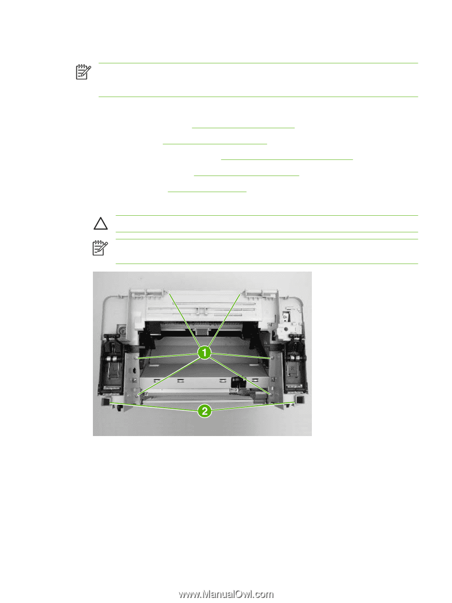
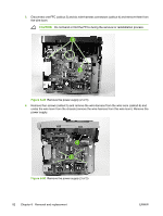
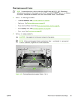
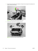
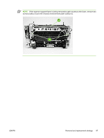
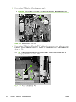
Scanner support frame NOTE Some photos show a device other than the HP LaserJet M1005 MFP. Repair and replacement procedures in this chapter are for the HP LaserJet M1005 MFP and are not affected by cosmetic differences (for example, the color of the covers) shown in these photos. 1. Remove the following assemblies ● Scanner assembly. See Scanner assembly on page 67. ● Left cover. See Device side covers on page 82. ● Rear cover and fuser cover. See Rear cover and fuser cover on page 86. ● Print cartridge door. See Print-cartridge door on page 85. ● Front cover. See Front cover on page 88. 2. Remove six screws (callout 1). CAUTION Be careful not to drop any screws into the device. NOTE If the scanner support frame is turned over after it is removed, the two scanner cushions (callout 2) might fall out and be misplaced. Figure 6-53 Remove the scanner support frame (1 of 3) ENWW Removal and replacement strategy 95
-
 1
1 -
2
-
3
-
4
-
5
-
6
-
7
-
8
-
9
-
10
-
11
-
12
-
13
-
14
-
15
-
16
-
17
-
18
-
19
-
20
-
21
-
22
-
23
-
24
-
25
-
26
-
27
-
28
-
29
-
30
-
31
-
32
-
33
-
34
-
35
-
36
-
37
-
38
-
39
-
40
-
41
-
42
-
43
-
44
-
45
-
46
-
47
-
48
-
49
-
50
-
51
-
52
-
53
-
54
-
55
-
56
-
57
-
58
-
59
-
60
-
61
-
62
-
63
-
64
-
65
-
66
-
67
-
68
-
69
-
70
-
71
-
72
-
73
-
74
-
75
-
76
-
77
-
78
-
79
-
80
-
81
-
82
-
83
-
84
-
85
-
86
-
87
-
88
-
89
-
90
-
91
-
92
-
93
-
94
-
95
-
96
-
97
-
98
-
99
-
100
-
101
-
102
-
103
-
104
-
105
-
 106
106 -
 107
107 -
 108
108 -
 109
109 -
 110
110 -
 111
111 -
 112
112 -
 113
113 -
 114
114 -
 115
115 -
 116
116 -
117
-
118
-
119
-
120
-
121
-
122
-
123
-
124
-
125
-
126
-
127
-
128
-
129
-
130
-
131
-
132
-
133
-
134
-
135
-
136
-
137
-
138
-
139
-
140
-
141
-
142
-
143
-
144
-
145
-
146
-
147
-
148
-
149
-
150
-
151
-
152
-
153
-
154
-
155
-
156
-
157
-
158
-
159
-
160
-
161
-
162
-
163
-
164
-
165
-
166
-
167
-
168
-
169
-
170
-
171
-
172
-
173
-
174
-
175
-
176
-
177
-
178
-
179
-
180
-
181
-
182
-
183
-
184
-
185
-
186
-
187
-
188
-
189
-
190
-
191
-
192
-
193
-
194
-
195
-
196
-
197
-
198
-
199
-
200
-
201
-
202
-
203
-
204
-
205
-
206
-
207
-
208
-
209
-
210
-
211
-
212
-
213
-
214
-
215
-
216
-
217
-
218
-
219
-
220
-
221
-
222
-
223
-
224
 |
 |