HP LaserJet M1005 Service Manual - Page 67
Image-formation system,
 |
View all HP LaserJet M1005 manuals
Add to My Manuals
Save this manual to your list of manuals |
Page 67 highlights
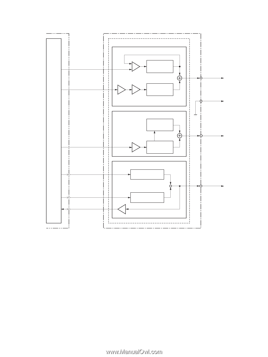
Engine controller PCB IC902 CPU PRPWM J902-10 J201-14 PRAC J902-9 J201-15 Power supply PCB High-voltage power supply circuit Primary charging bias circuit IC301 IC301 IC301 DC voltage generation circuit Combined AC voltage generation circuit DVAC J902-8 J201-16 TRPDC J902-6 J201-18 TRNDC J902-7 J201-17 TRCRNT J902-2 J201-22 Developing bias circuit DC voltage generation roller circuit IC301 Combined AC voltage generation circuit Transfer charging bias circuit Positive voltage generation circuit IC501 Negative voltage generation circuit Primary PR1 J304 charging roller Photosensitive J303 drum Developing DEV J301 cylinder Transfer TRS J302 charging Figure 5-3 High-voltage power supply circuit Image-formation system Laser printing requires the interaction of several different technologies including electronics, optics, and electrophotographics to provide a printed page. Each process functions independently and must be coordinated with the other device processes. Image formation consists of seven processes: ENWW Device functions 51
-
 1
1 -
2
-
3
-
4
-
5
-
6
-
7
-
8
-
9
-
10
-
11
-
12
-
13
-
14
-
15
-
16
-
17
-
18
-
19
-
20
-
21
-
22
-
23
-
24
-
25
-
26
-
27
-
28
-
29
-
30
-
31
-
32
-
33
-
34
-
35
-
36
-
37
-
38
-
39
-
40
-
41
-
42
-
43
-
44
-
45
-
46
-
47
-
48
-
49
-
50
-
51
-
52
-
53
-
54
-
55
-
56
-
57
-
58
-
59
-
60
-
61
-
 62
62 -
 63
63 -
 64
64 -
 65
65 -
 66
66 -
 67
67 -
 68
68 -
 69
69 -
 70
70 -
 71
71 -
 72
72 -
73
-
74
-
75
-
76
-
77
-
78
-
79
-
80
-
81
-
82
-
83
-
84
-
85
-
86
-
87
-
88
-
89
-
90
-
91
-
92
-
93
-
94
-
95
-
96
-
97
-
98
-
99
-
100
-
101
-
102
-
103
-
104
-
105
-
106
-
107
-
108
-
109
-
110
-
111
-
112
-
113
-
114
-
115
-
116
-
117
-
118
-
119
-
120
-
121
-
122
-
123
-
124
-
125
-
126
-
127
-
128
-
129
-
130
-
131
-
132
-
133
-
134
-
135
-
136
-
137
-
138
-
139
-
140
-
141
-
142
-
143
-
144
-
145
-
146
-
147
-
148
-
149
-
150
-
151
-
152
-
153
-
154
-
155
-
156
-
157
-
158
-
159
-
160
-
161
-
162
-
163
-
164
-
165
-
166
-
167
-
168
-
169
-
170
-
171
-
172
-
173
-
174
-
175
-
176
-
177
-
178
-
179
-
180
-
181
-
182
-
183
-
184
-
185
-
186
-
187
-
188
-
189
-
190
-
191
-
192
-
193
-
194
-
195
-
196
-
197
-
198
-
199
-
200
-
201
-
202
-
203
-
204
-
205
-
206
-
207
-
208
-
209
-
210
-
211
-
212
-
213
-
214
-
215
-
216
-
217
-
218
-
219
-
220
-
221
-
222
-
223
-
224
 |
 |