HP LaserJet M1005 Service Manual - Page 121
Fuser,
 |
View all HP LaserJet M1005 manuals
Add to My Manuals
Save this manual to your list of manuals |
Page 121 highlights
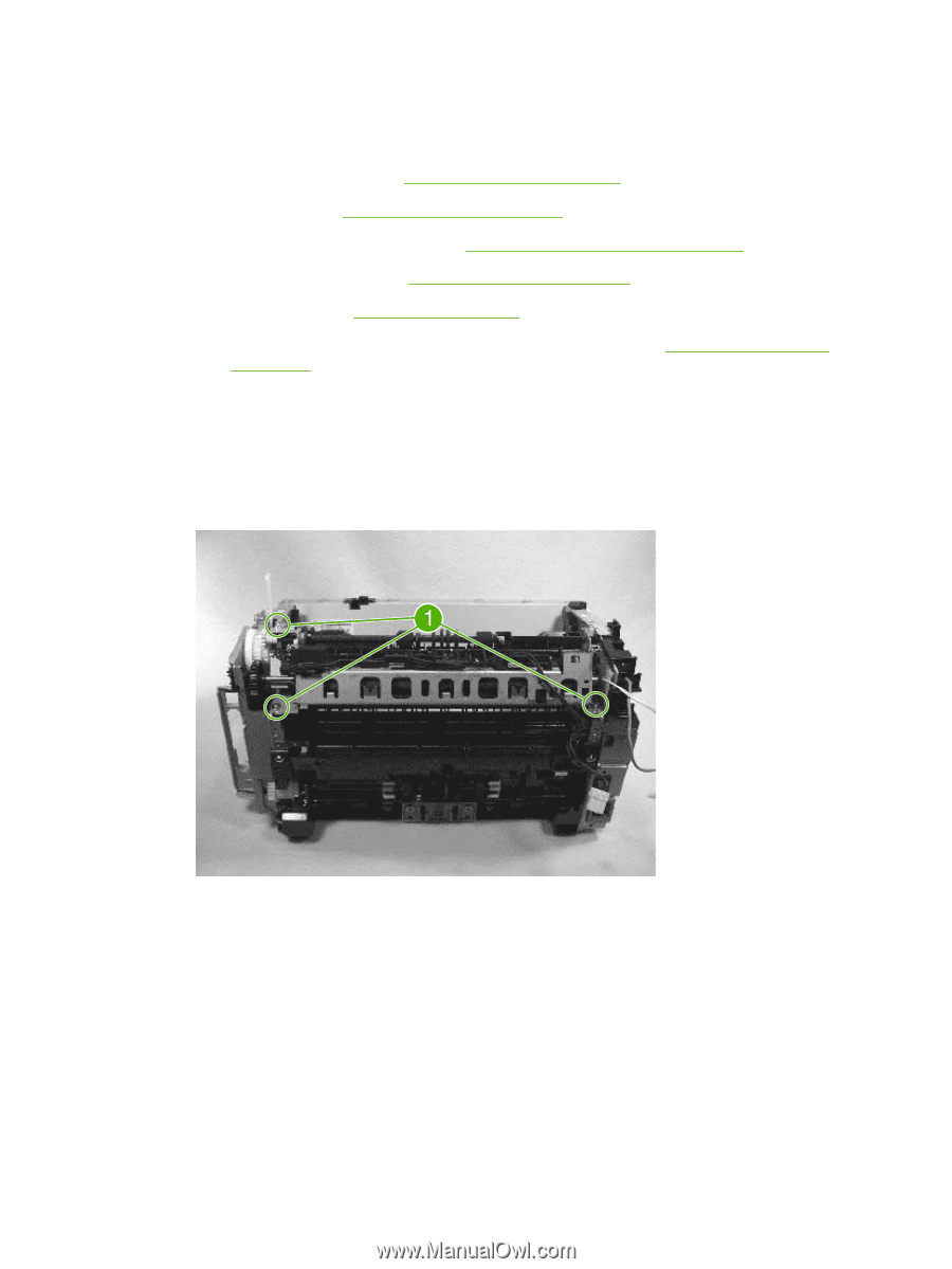
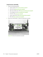
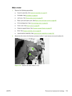
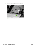
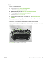
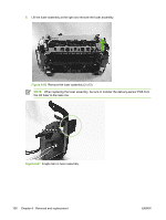
Fuser 1. Remove the following assemblies. ● Scanner assembly. See Scanner assembly on page 67. ● Left cover. See Device side covers on page 82. ● Rear cover and fuser cover. See Rear cover and fuser cover on page 86. ● Print cartridge door. See Print-cartridge door on page 85. ● Front cover. See Front cover on page 88. ● Scanner support frame and chassis reinforcement plate. See Scanner support frame on page 95. 2. Disconnect cables from near the top of the engine power assembly and disconnect the large grounding wire from the back of the device. 3. Disengage the wire-harnesses from the wire retainers to release the fuser assembly. 4. Remove three screws (callout 1; this figure shows the delivery-sensor PCB removed, which is not necessary). Figure 6-65 Remove the fuser assembly (1 of 2) ENWW Removal and replacement strategy 105
-
 1
1 -
2
-
3
-
4
-
5
-
6
-
7
-
8
-
9
-
10
-
11
-
12
-
13
-
14
-
15
-
16
-
17
-
18
-
19
-
20
-
21
-
22
-
23
-
24
-
25
-
26
-
27
-
28
-
29
-
30
-
31
-
32
-
33
-
34
-
35
-
36
-
37
-
38
-
39
-
40
-
41
-
42
-
43
-
44
-
45
-
46
-
47
-
48
-
49
-
50
-
51
-
52
-
53
-
54
-
55
-
56
-
57
-
58
-
59
-
60
-
61
-
62
-
63
-
64
-
65
-
66
-
67
-
68
-
69
-
70
-
71
-
72
-
73
-
74
-
75
-
76
-
77
-
78
-
79
-
80
-
81
-
82
-
83
-
84
-
85
-
86
-
87
-
88
-
89
-
90
-
91
-
92
-
93
-
94
-
95
-
96
-
97
-
98
-
99
-
100
-
101
-
102
-
103
-
104
-
105
-
106
-
107
-
108
-
109
-
110
-
111
-
112
-
113
-
114
-
115
-
 116
116 -
 117
117 -
 118
118 -
 119
119 -
 120
120 -
 121
121 -
 122
122 -
 123
123 -
 124
124 -
 125
125 -
 126
126 -
127
-
128
-
129
-
130
-
131
-
132
-
133
-
134
-
135
-
136
-
137
-
138
-
139
-
140
-
141
-
142
-
143
-
144
-
145
-
146
-
147
-
148
-
149
-
150
-
151
-
152
-
153
-
154
-
155
-
156
-
157
-
158
-
159
-
160
-
161
-
162
-
163
-
164
-
165
-
166
-
167
-
168
-
169
-
170
-
171
-
172
-
173
-
174
-
175
-
176
-
177
-
178
-
179
-
180
-
181
-
182
-
183
-
184
-
185
-
186
-
187
-
188
-
189
-
190
-
191
-
192
-
193
-
194
-
195
-
196
-
197
-
198
-
199
-
200
-
201
-
202
-
203
-
204
-
205
-
206
-
207
-
208
-
209
-
210
-
211
-
212
-
213
-
214
-
215
-
216
-
217
-
218
-
219
-
220
-
221
-
222
-
223
-
224
 |
 |