Kyocera TASKalfa 5002i Fax System 12 Operation Guide R4 2016.08 - Page 18
Part Names and Functions, Machine
 |
View all Kyocera TASKalfa 5002i manuals
Add to My Manuals
Save this manual to your list of manuals |
Page 18 highlights
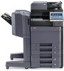
Before Using the Fax Machine > Part Names and Functions Part Names and Functions Machine This chapter explains the names of parts when the machine is used as a fax machine. For the parts required when functions other than FAX are used, refer to the following: Machine's Operation Guide 1 2 3 2552ci/3252ci/3552ci/4002i/4052ci/ 5002i/5052ci/6002i/6052ci 44 55 66 3011i/3511i 4 1 2 5 7002i/7052ci/ 8002i/8052ci 6 1 2 3 3 1 Operation panel 2 Power switch 3 MP (Multipurpose) tray 4 LINE connector (L2) 5 LINE connector (L1) 6 TEL connector (T1) Perform the fax operation with this panel. Set this switch to the ON side when performing the fax or copier operation. The touch panel lights to enable operation. Set the paper in this tray when using a type of paper other than the cassette (e.g., when using special paper). If you install 2 optional FAX Kits (Dual FAX option), you can use Port 2. Connect the modular cord for the telephone line to this connector. Connect the modular cord for the telephone line to this connector. This connector is Port 1. When using a commercially available telephone set, connect the modular cord to this connector. IMPORTANT You cannot automatically receive a fax when the power switch is turned off. 2-2
-
 1
1 -
2
-
3
-
4
-
5
-
6
-
7
-
8
-
9
-
10
-
11
-
12
-
 13
13 -
 14
14 -
 15
15 -
 16
16 -
 17
17 -
 18
18 -
 19
19 -
 20
20 -
 21
21 -
 22
22 -
 23
23 -
24
-
25
-
26
-
27
-
28
-
29
-
30
-
31
-
32
-
33
-
34
-
35
-
36
-
37
-
38
-
39
-
40
-
41
-
42
-
43
-
44
-
45
-
46
-
47
-
48
-
49
-
50
-
51
-
52
-
53
-
54
-
55
-
56
-
57
-
58
-
59
-
60
-
61
-
62
-
63
-
64
-
65
-
66
-
67
-
68
-
69
-
70
-
71
-
72
-
73
-
74
-
75
-
76
-
77
-
78
-
79
-
80
-
81
-
82
-
83
-
84
-
85
-
86
-
87
-
88
-
89
-
90
-
91
-
92
-
93
-
94
-
95
-
96
-
97
-
98
-
99
-
100
-
101
-
102
-
103
-
104
-
105
-
106
-
107
-
108
-
109
-
110
-
111
-
112
-
113
-
114
-
115
-
116
-
117
-
118
-
119
-
120
-
121
-
122
-
123
-
124
-
125
-
126
-
127
-
128
-
129
-
130
-
131
-
132
-
133
-
134
-
135
-
136
-
137
-
138
-
139
-
140
-
141
-
142
-
143
-
144
-
145
-
146
-
147
-
148
-
149
-
150
-
151
-
152
-
153
-
154
-
155
-
156
-
157
-
158
-
159
-
160
-
161
-
162
-
163
-
164
-
165
-
166
-
167
-
168
-
169
-
170
-
171
-
172
-
173
-
174
-
175
-
176
-
177
-
178
-
179
-
180
-
181
-
182
-
183
-
184
-
185
-
186
-
187
-
188
-
189
-
190
-
191
-
192
-
193
-
194
-
195
-
196
-
197
-
198
-
199
-
200
-
201
-
202
-
203
-
204
-
205
-
206
-
207
-
208
-
209
-
210
-
211
-
212
-
213
-
214
-
215
-
216
-
217
-
218
-
219
-
220
-
221
-
222
-
223
-
224
-
225
-
226
-
227
-
228
-
229
-
230
-
231
-
232
-
233
-
234
-
235
-
236
-
237
-
238
-
239
-
240
-
241
-
242
-
243
-
244
-
245
-
246
-
247
-
248
-
249
-
250
-
251
-
252
-
253
-
254
-
255
-
256
-
257
-
258
-
259
-
260
-
261
 |
 |
