Lexmark W820 Service Manual - Page 109

Removal and Replacement Procedures, Notations in the text
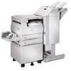
Page 109 highlights

4025-Finisher 4. Removal and Replacement Procedures This section contains the removal and replacement procedures for major parts within the printer Finisher. Before you begin any Removal and Replacement Procedure: 1. Switch OFF the printer power. 2. Disconnect the AC power cord from the electrical outlet. 3. Wear an electrostatic discharge wrist strap to protect sensitive printer parts from damage. Note: Names of parts that appear in the Removals section may not be exactly the same as the names appear in the parts list. For example, an RRP for the MP feeder Tray Assembly may appear on the parts list as Tray Assembly MP feeder. Always reinstall the correct type and size screws. Using the wrong screw can damage tapped holes. Do not use excessive force to either remove or install a part. Notations in the text • Locations, such as R or right assume you are facing the printer console panel. • The notation "(Figure X)" points to the illustration that corresponds to the repair you are performing. • Arrows in an illustration show direction of movement when removing a component. Removal and Replacement Procedures 4-1

  • 1
  • 2
  • 3
  • 4
  • 5
  • 6
  • 7
  • 8
  • 9
  • 10
  • 11
  • 12
  • 13
  • 14
  • 15
  • 16
  • 17
  • 18
  • 19
  • 20
  • 21
  • 22
  • 23
  • 24
  • 25
  • 26
  • 27
  • 28
  • 29
  • 30
  • 31
  • 32
  • 33
  • 34
  • 35
  • 36
  • 37
  • 38
  • 39
  • 40
  • 41
  • 42
  • 43
  • 44
  • 45
  • 46
  • 47
  • 48
  • 49
  • 50
  • 51
  • 52
  • 53
  • 54
  • 55
  • 56
  • 57
  • 58
  • 59
  • 60
  • 61
  • 62
  • 63
  • 64
  • 65
  • 66
  • 67
  • 68
  • 69
  • 70
  • 71
  • 72
  • 73
  • 74
  • 75
  • 76
  • 77
  • 78
  • 79
  • 80
  • 81
  • 82
  • 83
  • 84
  • 85
  • 86
  • 87
  • 88
  • 89
  • 90
  • 91
  • 92
  • 93
  • 94
  • 95
  • 96
  • 97
  • 98
  • 99
  • 100
  • 101
  • 102
  • 103
  • 104
  • 105
  • 106
  • 107
  • 108
  • 109
  • 110
  • 111
  • 112
  • 113
  • 114
  • 115
  • 116
  • 117
  • 118
  • 119
  • 120
  • 121
  • 122
  • 123
  • 124
  • 125
  • 126
  • 127
  • 128
  • 129
  • 130
  • 131
  • 132
  • 133
  • 134
  • 135
  • 136
  • 137
  • 138
  • 139
  • 140
  • 141
  • 142
  • 143
  • 144
  • 145
  • 146
  • 147
  • 148
  • 149
  • 150
  • 151
  • 152
  • 153
  • 154
  • 155
  • 156
  • 157
  • 158
  • 159
  • 160
  • 161
  • 162
  • 163
  • 164
  • 165
  • 166
  • 167
  • 168
  • 169
  • 170
  • 171
  • 172
  • 173
  • 174
  • 175
  • 176
  • 177
  • 178
  • 179
  • 180
  • 181
  • 182
  • 183
  • 184
  • 185
  • 186
  • 187
  • 188
  • 189
  • 190
  • 191
  • 192
  • 193
  • 194
  • 195
  • 196
  • 197
  • 198
  • 199
  • 200
  • 201
  • 202
  • 203
  • 204
  • 205
  • 206
  • 207
  • 208
  • 209
  • 210
  • 211
  • 212
  • 213
  • 214
  • 215
  • 216
  • 217
  • 218
  • 219
  • 220
  • 221
  • 222
  • 223
  • 224
  • 225
  • 226
  • 227
  • 228
  • 229
  • 230
  • 231
  • 232
  • 233
  • 234
  • 235
  • 236
  • 237
  • 238
  • 239
  • 240
  • 241
  • 242
  • 243
  • 244
  • 245
  • 246
  • 247
  • 248
  • 249
  • 250
  • 251
  • 252
  • 253
  • 254
  • 255
  • 256
  • 257
  • 258
  • 259
  • 260
  • 261
  • 262
  • 263
  • 264
  • 265
  • 266
  • 267
  • 268
  • 269
  • 270
  • 271
  • 272
  • 273
  • 274
  • 275
  • 276
  • 277
  • 278
  • 279
  • 280
  • 281
  • 282
  • 283
  • 284
  • 285
  • 286
  • 287
  • 288
  • 289
  • 290
  • 291
  • 292
  • 293
  • 294
  • 295
  • 296
  • 297
  • 298
  • 299
  • 300
  • 301
  • 302
  • 303
  • 304
  • 305
  • 306
  • 307
  • 308
  • 309
  • 310
  • 311
  • 312
  • 313
  • 314
  • 315
  • 316
  • 317
  • 318
  • 319
  • 320
  • 321
  • 322
  • 323
  • 324
  • 325
  • 326
  • 327
  • 328
  • 329
  • 330
  • 331
  • 332
  • 333
  • 334
  • 335
  • 336
  • 337
  • 338

Removal and Replacement Procedures
4-1
4025-Finisher
4.
Removal and Replacement Procedures
This section contains the removal and replacement procedures for major parts within the
printer Finisher. Before you begin any Removal and Replacement Procedure:
1.
Switch OFF the printer power.
2.
Disconnect the AC power cord from the electrical outlet.
3.
Wear an electrostatic discharge wrist strap to protect sensitive printer parts from
damage.
Note:
Names of parts that appear in the Removals section may not be exactly the same
as the names appear in the parts list. For example, an RRP for the MP feeder Tray
Assembly may appear on the parts list as Tray Assembly MP feeder. Always reinstall the
correct type and size screws. Using the wrong screw can damage tapped holes. Do not
use excessive force to either remove or install a part.
Notations in the text
Locations, such as R or right assume you are facing the printer console panel.
The notation
(Figure X)
points to the illustration that corresponds to the repair you
are performing.
Arrows in an illustration show direction of movement when removing a component.