Lexmark W820 Service Manual - Page 208

Finisher, and remove the Cover Upper Left Assembly., Mount the Inner Cover and the Stapler Assembly.
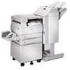
Page 208 highlights

4025-Finisher Removal 1. Remove the Cartridge and the Bottle Assembly-Dust. 2. Remove the Cover-Jogging. 3. Remove the Cover-Top, Front and Cover-Top, Rear. 4. Remove the Cover-Rear. 5. Remove the Cover-Open, Front, Cover-Front and Kit Stud Cover. 6. Remove the Stapler Assembly. 7. Remove the Inner Cover. 8. Remove six screws that secure the Cover Upper Left Assembly to the frame of the Finisher, and remove the Cover Upper Left Assembly. 9. Remove the Latch Assembly and Switch Docking. 10. Remove the Stapler Assembly. 11. Unhook the Spring on the back of the stapler. (Figure 1) 12. Loosen the Screw and slacken the belt tension. 13. Slide the small plate toward the front. (Figure 2) 14. Open the small plate of the stapler, release two clamps, and disconnect the connector (P/J 10,11,12) connected to the Sensor Assembly-Swing and Sensor. (Figure 3) 15. Disconnect the connector (CN 10) connected to the Stapler Assembly. (Figure 4) 16. Remove two screws that secure the Stapler Bottom Cover, and shift the Stapler Bottom Cover toward the right to remove, and pull the connector out of the hole in the Stapler Assembly. 17. Release one clamp on the small plate, and disconnect the connector (P/J CN9) connected to the Motor Assembly-Swing. Replacement 1. Connect the connector (P/J CN9) of the Motor Assembly-Swing, and bundle the wires with a clamp. 2. Place the connector (P/J CN10) of the Stapler harness assembly through the hole and connect it to the Stapler Assembly. 3. Open the small plate of the stapler, connect three connectors (P/J 10,11,12), and bundle the wires with two clamps. (Figure 3) 4. Close the small plate together with the Stapler Holder. (Figure 2) 5. Adjust the belt tension by relocating the tension roller, and then tighten the screw. (Figure 1) 6. Mount the Stapler Assembly. 7. Mount the Latch Assembly and Switch Docking. 8. Align the Cover Upper Left Assembly, with the mounting position in the frame of the Finisher, and secure them with six screws. 9. Mount the Inner Cover and the Stapler Assembly. 10. Mount the Cover-Open, Front, Cover-Front and Kit Stud Cover. 11. Mount the Cover-Rear. 12. Mount the Cover-Top, Front and Cover-Top, Rear. 13. Mount the Cover-Jogging. 14. Mount the Bottle Assembly-Dust. 15. Mount the Cartridge. 4-100 Service Manual

  • 1
  • 2
  • 3
  • 4
  • 5
  • 6
  • 7
  • 8
  • 9
  • 10
  • 11
  • 12
  • 13
  • 14
  • 15
  • 16
  • 17
  • 18
  • 19
  • 20
  • 21
  • 22
  • 23
  • 24
  • 25
  • 26
  • 27
  • 28
  • 29
  • 30
  • 31
  • 32
  • 33
  • 34
  • 35
  • 36
  • 37
  • 38
  • 39
  • 40
  • 41
  • 42
  • 43
  • 44
  • 45
  • 46
  • 47
  • 48
  • 49
  • 50
  • 51
  • 52
  • 53
  • 54
  • 55
  • 56
  • 57
  • 58
  • 59
  • 60
  • 61
  • 62
  • 63
  • 64
  • 65
  • 66
  • 67
  • 68
  • 69
  • 70
  • 71
  • 72
  • 73
  • 74
  • 75
  • 76
  • 77
  • 78
  • 79
  • 80
  • 81
  • 82
  • 83
  • 84
  • 85
  • 86
  • 87
  • 88
  • 89
  • 90
  • 91
  • 92
  • 93
  • 94
  • 95
  • 96
  • 97
  • 98
  • 99
  • 100
  • 101
  • 102
  • 103
  • 104
  • 105
  • 106
  • 107
  • 108
  • 109
  • 110
  • 111
  • 112
  • 113
  • 114
  • 115
  • 116
  • 117
  • 118
  • 119
  • 120
  • 121
  • 122
  • 123
  • 124
  • 125
  • 126
  • 127
  • 128
  • 129
  • 130
  • 131
  • 132
  • 133
  • 134
  • 135
  • 136
  • 137
  • 138
  • 139
  • 140
  • 141
  • 142
  • 143
  • 144
  • 145
  • 146
  • 147
  • 148
  • 149
  • 150
  • 151
  • 152
  • 153
  • 154
  • 155
  • 156
  • 157
  • 158
  • 159
  • 160
  • 161
  • 162
  • 163
  • 164
  • 165
  • 166
  • 167
  • 168
  • 169
  • 170
  • 171
  • 172
  • 173
  • 174
  • 175
  • 176
  • 177
  • 178
  • 179
  • 180
  • 181
  • 182
  • 183
  • 184
  • 185
  • 186
  • 187
  • 188
  • 189
  • 190
  • 191
  • 192
  • 193
  • 194
  • 195
  • 196
  • 197
  • 198
  • 199
  • 200
  • 201
  • 202
  • 203
  • 204
  • 205
  • 206
  • 207
  • 208
  • 209
  • 210
  • 211
  • 212
  • 213
  • 214
  • 215
  • 216
  • 217
  • 218
  • 219
  • 220
  • 221
  • 222
  • 223
  • 224
  • 225
  • 226
  • 227
  • 228
  • 229
  • 230
  • 231
  • 232
  • 233
  • 234
  • 235
  • 236
  • 237
  • 238
  • 239
  • 240
  • 241
  • 242
  • 243
  • 244
  • 245
  • 246
  • 247
  • 248
  • 249
  • 250
  • 251
  • 252
  • 253
  • 254
  • 255
  • 256
  • 257
  • 258
  • 259
  • 260
  • 261
  • 262
  • 263
  • 264
  • 265
  • 266
  • 267
  • 268
  • 269
  • 270
  • 271
  • 272
  • 273
  • 274
  • 275
  • 276
  • 277
  • 278
  • 279
  • 280
  • 281
  • 282
  • 283
  • 284
  • 285
  • 286
  • 287
  • 288
  • 289
  • 290
  • 291
  • 292
  • 293
  • 294
  • 295
  • 296
  • 297
  • 298
  • 299
  • 300
  • 301
  • 302
  • 303
  • 304
  • 305
  • 306
  • 307
  • 308
  • 309
  • 310
  • 311
  • 312
  • 313
  • 314
  • 315
  • 316
  • 317
  • 318
  • 319
  • 320
  • 321
  • 322
  • 323
  • 324
  • 325
  • 326
  • 327
  • 328
  • 329
  • 330
  • 331
  • 332
  • 333
  • 334
  • 335
  • 336
  • 337
  • 338

4-100
Service Manual
4025-Finisher
Removal
1.
Remove the Cartridge and the Bottle Assembly-Dust.
2.
Remove the Cover-Jogging.
3.
Remove the Cover-Top, Front and Cover-Top, Rear.
4.
Remove the Cover-Rear.
5.
Remove the Cover-Open, Front, Cover-Front and Kit Stud Cover.
6.
Remove the Stapler Assembly.
7.
Remove the Inner Cover.
8.
Remove six screws that secure the Cover Upper Left Assembly to the frame of the
Finisher, and remove the Cover Upper Left Assembly.
9.
Remove the Latch Assembly and Switch Docking.
10.
Remove the Stapler Assembly.
11.
Unhook the Spring on the back of the stapler. (Figure 1)
12.
Loosen the Screw and slacken the belt tension.
13.
Slide the small plate toward the front. (Figure 2)
14.
Open the small plate of the stapler, release two clamps, and disconnect the
connector (P/J 10,11,12) connected to the Sensor Assembly-Swing and Sensor.
(Figure 3)
15.
Disconnect the connector (CN 10) connected to the Stapler Assembly. (Figure 4)
16.
Remove two screws that secure the Stapler Bottom Cover, and shift the Stapler
Bottom Cover toward the right to remove, and pull the connector out of the hole in
the Stapler Assembly.
17.
Release one clamp on the small plate, and disconnect the connector (P/J CN9)
connected to the Motor Assembly-Swing.
Replacement
1.
Connect the connector (P/J CN9) of the Motor Assembly-Swing, and bundle the
wires with a clamp.
2.
Place the connector (P/J CN10) of the Stapler harness assembly through the hole
and connect it to the Stapler Assembly.
3.
Open the small plate of the stapler, connect three connectors (P/J 10,11,12), and
bundle the wires with two clamps. (Figure 3)
4.
Close the small plate together with the Stapler Holder. (Figure 2)
5.
Adjust the belt tension by relocating the tension roller, and then tighten the screw.
(Figure 1)
6.
Mount the Stapler Assembly.
7.
Mount the Latch Assembly and Switch Docking.
8.
Align the Cover Upper Left Assembly, with the mounting position in the frame of the
Finisher, and secure them with six screws.
9.
Mount the Inner Cover and the Stapler Assembly.
10.
Mount the Cover-Open, Front, Cover-Front and Kit Stud Cover.
11.
Mount the Cover-Rear.
12.
Mount the Cover-Top, Front and Cover-Top, Rear.
13.
Mount the Cover-Jogging.
14.
Mount the Bottle Assembly-Dust.
15.
Mount the Cartridge.