Netgear AC1750 User Manual - Page 13
Ports, Buttons, and Connectors on the Back Panel
 |
View all Netgear AC1750 manuals
Add to My Manuals
Save this manual to your list of manuals |
Page 13 highlights
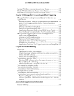
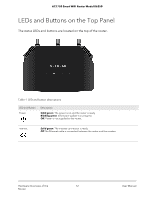
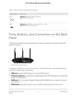
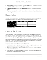
AC1750 Smart WiFi Router Model R6350 Table 1. LED and button descriptions (Continued) LED and Button WiFi Description Solid green. The WiFi radio is operating. Off. The WiFi radios are off. USB Solid green. A USB device is connected and is ready. Off. No USB device is connected. Ports, Buttons, and Connectors on the Back Panel The back panel of the router provides ports, buttons, antenna connectors, and a DC power connector. Figure 2. Router back panel In addition to the three antenna connectors, viewed from left to right, the back panel contains the following components: • USB port. Use the USB 2.0 port to connect USB devices. • Ethernet LAN ports. Use the four Gigabit Ethernet RJ-45 LAN ports to connect the router to LAN devices. • WAN port. Use the yellow Gigabit Ethernet RJ-45 WAN port to connect the router to a modem. • WPS button. Use this button to connect WPS-enabled devices to the router. Hardware Overview of the 13 Router User Manual
-
 1
1 -
2
-
3
-
4
-
5
-
6
-
7
-
 8
8 -
 9
9 -
 10
10 -
 11
11 -
 12
12 -
 13
13 -
 14
14 -
 15
15 -
 16
16 -
 17
17 -
 18
18 -
19
-
20
-
21
-
22
-
23
-
24
-
25
-
26
-
27
-
28
-
29
-
30
-
31
-
32
-
33
-
34
-
35
-
36
-
37
-
38
-
39
-
40
-
41
-
42
-
43
-
44
-
45
-
46
-
47
-
48
-
49
-
50
-
51
-
52
-
53
-
54
-
55
-
56
-
57
-
58
-
59
-
60
-
61
-
62
-
63
-
64
-
65
-
66
-
67
-
68
-
69
-
70
-
71
-
72
-
73
-
74
-
75
-
76
-
77
-
78
-
79
-
80
-
81
-
82
-
83
-
84
-
85
-
86
-
87
-
88
-
89
-
90
-
91
-
92
-
93
-
94
-
95
-
96
-
97
-
98
-
99
-
100
-
101
-
102
-
103
-
104
-
105
-
106
-
107
-
108
-
109
-
110
-
111
-
112
-
113
-
114
-
115
-
116
-
117
-
118
-
119
-
120
-
121
-
122
-
123
-
124
-
125
-
126
-
127
-
128
-
129
-
130
-
131
-
132
-
133
-
134
-
135
-
136
-
137
-
138
-
139
-
140
-
141
-
142
-
143
-
144
-
145
-
146
-
147
-
148
-
149
-
150
-
151
-
152
-
153
-
154
-
155
-
156
-
157
-
158
-
159
-
160
-
161
-
162
-
163
-
164
-
165
-
166
-
167
-
168
-
169
-
170
-
171
-
172
-
173
-
174
-
175
-
176
-
177
-
178
-
179
-
180
-
181
-
182
-
183
-
184
-
185
-
186
-
187
-
188
-
189
-
190
-
191
-
192
-
193
-
194
-
195
-
196
-
197
-
198
-
199
-
200
-
201
-
202
-
203
-
204
 |
 |